Articles | Volume 9, issue 1
https://doi.org/10.5194/jsss-9-7-2020
Regular research article
 | 
21 Jan 2020
Regular research article |  | 21 Jan 2020

Pedestrian navigation system based on the inertial measurement unit sensor for outdoor and indoor environments

Marcin Uradzinski and Hang Guo
Abstract

With the continuous improvement of the hardware level of the inertial measurement unit (IMU), indoor pedestrian dead reckoning (PDR) using an inertial device has been paid more and more attention. Typical PDR system position estimation is based on acceleration obtained from accelerometers to measure the step count, estimate step length and generate the position with the heading received from angular sensors (magnetometers and gyroscopes). Unfortunately, collected signals are very responsive to the alignment of sensor devices, built-in instrumental errors and distortions from the surrounding environment.

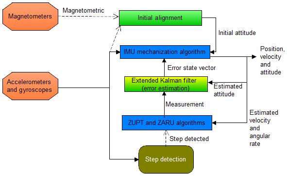
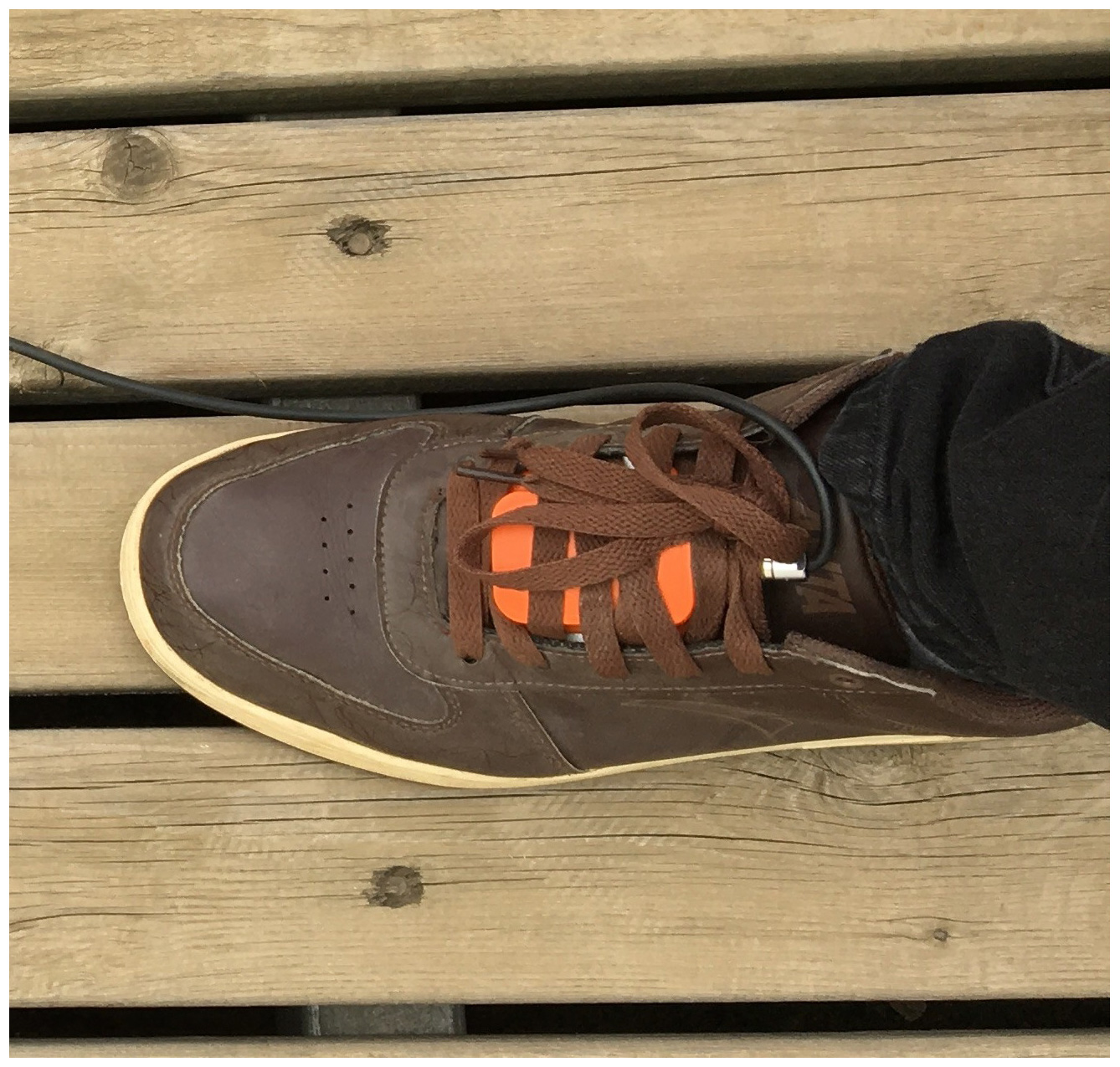
In our work, a pedestrian positioning method using step detection based on a shoe-mounted inertial unit is arranged and put to the test, and the final results are analyzed. The extended Kalman filter (EKF) provides estimation of the errors which are acquired by the XSENS IMU sensor biases. The EKF is revised with acceleration and angular rate computations by the ZUPT (zero velocity update) and ZARU (zero angular rate update) algorithms. The step detection associated with these two solutions is the perfect choice to calculate the current position and distance walked and to estimate the IMU sensors' collected errors by using EKF.

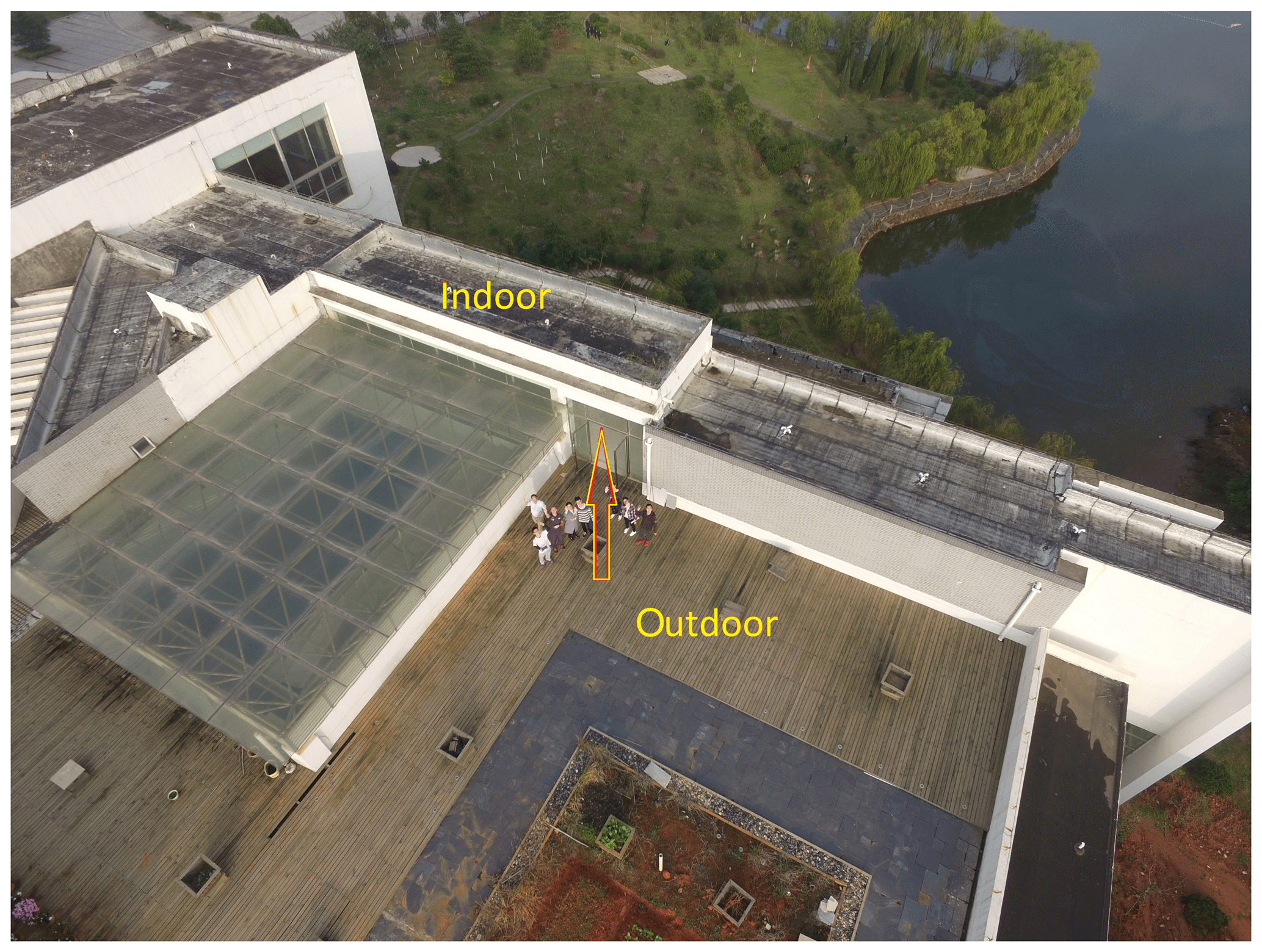
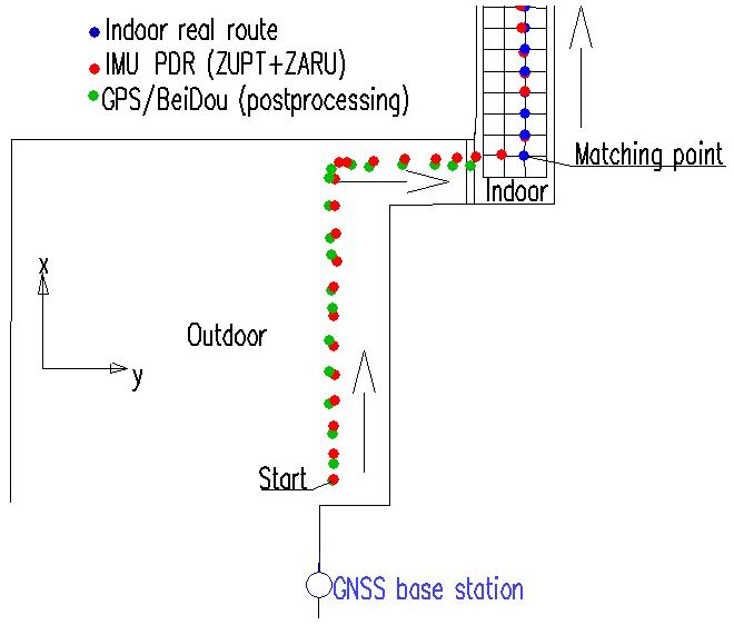
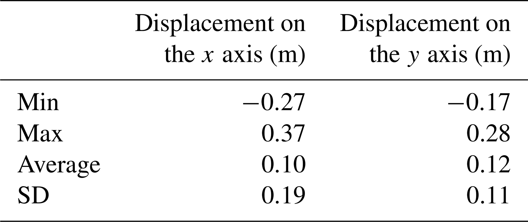
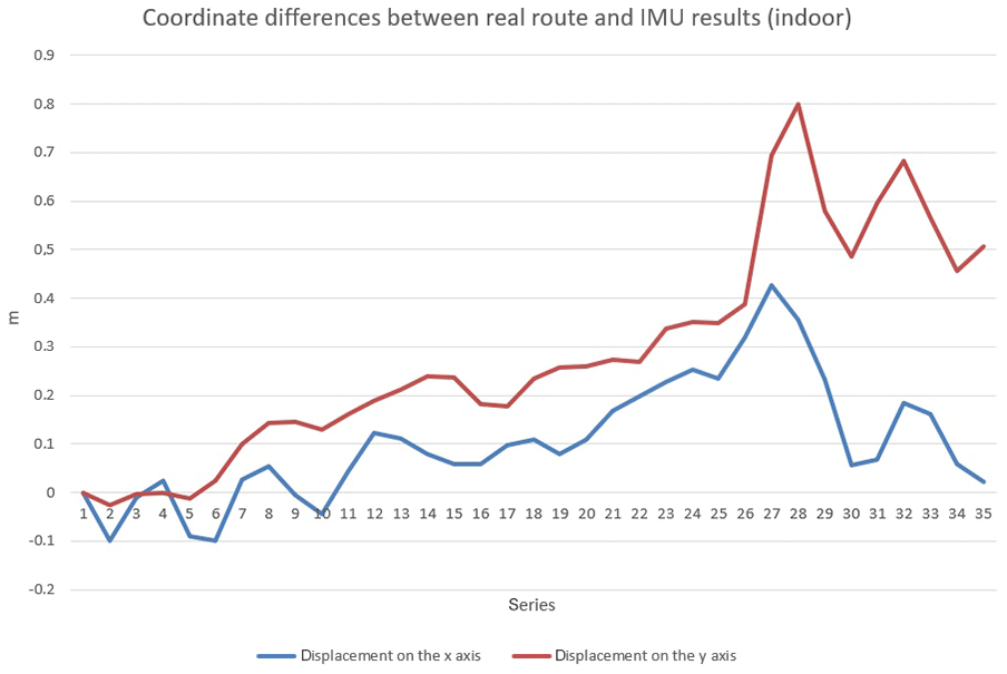
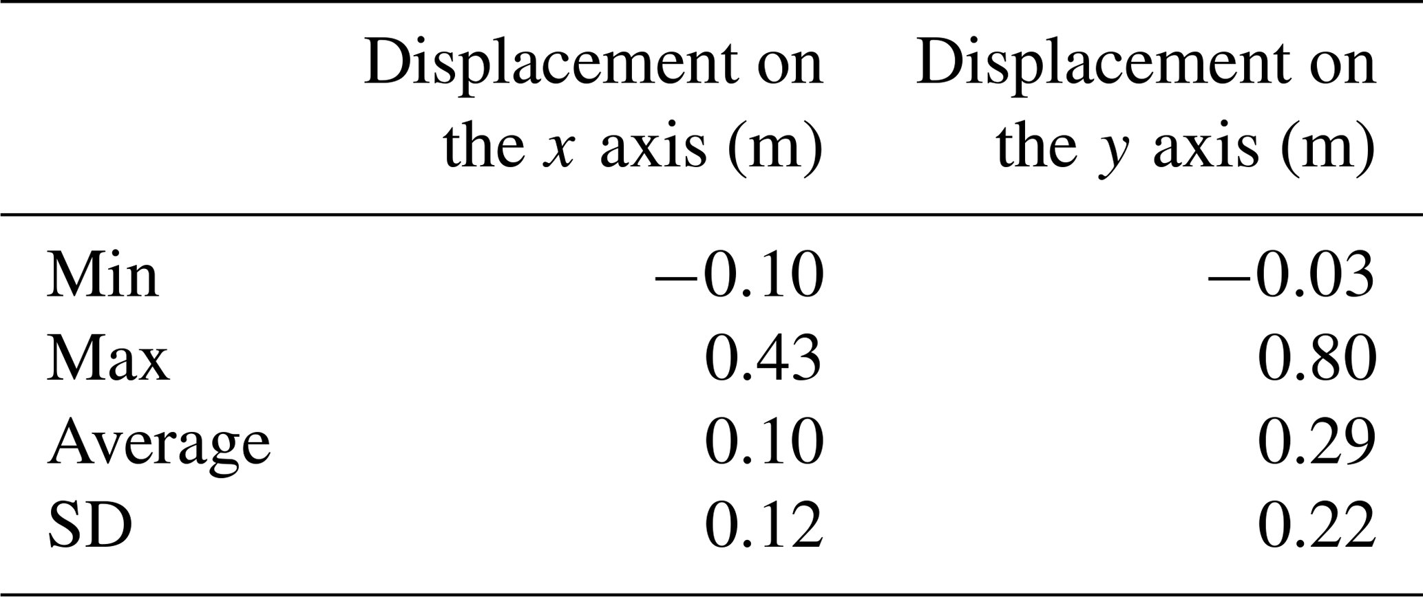
The test with a shoe-mounted IMU device was performed and analyzed in order to check the performance of the recommended method. The combined PDR final results were compared to GPS/Beidou postprocessing kinematic results (outdoor environment) and to a real route which was prepared and calculated for an indoor environment. After the comparison, the results show that the accuracy of the regular-speed walking under ZUPT and ZARU combination in the case of outdoor positioning did not go beyond 0.19 m (SD) and for indoor positioning accuracy did not exceed 0.22 m (SD). The authors are conscious that built-in drift errors coming from accelerometers and gyroscopes, as well as the final position obtained by XSENS IMU, are only stable for a short time period. Based on this consideration, our future work will be focused on supporting the methods presented with radio technologies (WiFi) or image-based solutions to correct all IMU imperfections.

Dates
1 Introduction

The conventional pedestrian dead reckoning (PDR) system is based on acceleration obtained from accelerometers to measure the step count, estimate step length and generate the position with the heading received from angular sensors (magnetometers and gyroscopes). Such a solution can be used in almost any location: airports, mines or shopping malls. It can also be very helpful to guide blind pedestrians, emergency rescue workers or firefighters (Chen et al., 2015; Deng et al., 2015; He et al., 2013; Placer and Kovacic, 2013). However, collected signals are very responsive to the alignment of sensor devices, the built-in instrumental errors and distortions from the surrounding environment (Morales et al., 2016; Zhang et al., 2014).

Various dead reckoning solutions based on the inertial measurement unit (IMU) have been proposed by scientists. In Ruiz et al. (2012) and Xu et al. (2015) a person's position is determined using an inertial navigation algorithm (INA). The basic INA uses Kalman filtering to estimate the walker's trajectory using gyroscope and accelerometer outputs. For the reason that positioning accuracy decreases over time, supplementary sensors are usually used with IMU such as a time of arrival based on the local positioning system (LPS) – a radio frequency based system with inertial sensor supplementation (Amendolare et al., 2008). Such a solution is used in situations where accuracy can be severely degraded at particular locations within a building. Wireless sensor networks, such as ZigBee technology, can provide the RSSI (received signal strength indicator), which can be used for positioning, especially indoor positioning. This positioning method can use the signal strength indication between the reference nodes and positioning nodes, as well as design algorithms for positioning. In the wireless sensor networks, according to measuring the distance between the nodes in the positioning process, the positioning modes are divided into two categories: range-based and range-free positioning modes (Uradzinski et al., 2017; Zhang et al., 2014). Another solution is to combine inertial sensors with distance measurement sensors. In Duong and Suh (2015) the distance sensor measures the distance by measuring the time of flight of infrared light. This sensor is most often used as a proximity sensor in smartphones.

In this paper, a pedestrian positioning method using step detection based on a shoe-mounted inertial unit is arranged and put to the test, and the final results are analyzed. The authors use extended Kalman filter (EKF), which provides estimation of the errors which are acquired by the XSENS IMU sensor biases.

2 PDR positioning method and system overview

In the presented work, an inertial pedestrian positioning method using step detection based on a shoe-mounted inertial unit is arranged. The EKF provides estimation of the errors which are accumulated by the XSENS IMU sensor biases (Foxlin, 2005). The EKF is revised with acceleration and angular rate computations by the zero velocity update (ZUPT) and zero angular rate update (ZARU) algorithms to separately detect the foot is on the floor. The step detection associated with these two solutions allows sensor biases to be compensated for with the estimated errors. For this reason, the use of ZUPT and ZARU combinations frequently bounds many of the errors, and therefore nearly all low cost IMU devices can be used for pedestrian navigation.

The proposed pedestrian positioning system program is based on five stages (Fig. 1):

  • a.

    During the first few minutes an initial alignment is conducted which calculates the initial attitude with the static data of accelerometers and magnetometers.

  • b.

    Navigation parameters (velocity, attitude and finally position) are computed using the IMU mechanization algorithm.

  • c.

    Information is provided on when the foot touches the ground (angular rate and velocity of IMU are equal to zero) using the IMU detection algorithm.

  • d.

    When a step is recognized, ZUPT and ZARU algorithms feed the EKF with measured errors.

  • e.

    EKF counts the errors and gives reaction to the IMU mechanization algorithm.

https://www.j-sens-sens-syst.net/9/7/2020/jsss-9-7-2020-f01

Figure 1The framework of pedestrian dead reckoning indoor positioning.

Download

3 Alignment of IMU sensor

The initial alignment of an inertial sensor is carried out in two stages – leveling and gyro-compassing. The leveling step brings up the roll and pitch information using the acceleration. The gyro-compassing step gives heading information using the angular rate. Unfortunately, heading has a meaning error, because the bias and noise of gyroscopes are larger than the value of the Earth's rotation rate for the IMU MEMS device (Microelectromechanical Systems – technology of microscopic devices with moving parts). In such a case, the initial alignment of inertial sensors is realized for the first few minutes using the static data of accelerometers and magnetometers (method for heading).

In static state, the roll ϕ and pitch θ angles are

(1)θ=-arcsinaibxb/g,(2)ϕ=arcsinaibyb/(gcosθ),

where (aibxb) and (aibyb) express the x and y axis output of accelerometers, respectively, in the body frame, i.e., the body fixed to the device (b is defined as north–west–up in the right-handed Cartesian coordinate system) (Xens Technologies B. V., 2010), and g represents the acceleration of gravity.

While using the magnetometers to obtain the heading, we need to compute the intensity of the magnetic field in the navigation frame (n is defined as north–west–up) with the magnetometers' outputs:

(3)Mnx=Mbxcosθ+Mbysinϕ+Mbzcosϕ,(4)Mny=Mbycosφ-Mbz,

where Mbx, Mby and Mbz denote the x, y and z axis output of magnetometers separately. Mnx and Mny represent the x and y axis of magnetic field intensity in navigation frame.

Therefore, the heading angle ψ is

(5) ψ = tan - 1 M n y / M n x - M d ,

where Md is the Earth magnetic declination at a given position of IMU.

4 Step detection

The movement of a foot-mounted IMU can be divided into two phases when a person walks. The first one is the swing phase, which means the foot-mounted IMU is moving. The other is the stance phase, which means the foot-mounted IMU is on the ground. The angular and linear velocity of the foot-mounted IMU must be very close to zero in theory in the stance phase. So the angular and linear velocity of the foot-mounted IMU can be used as the measurements of EKF (Jimenez et al., 2010). This is the main idea of ZUPT and ZARU. We use a multi-condition algorithm to detect steps using accelerometer and gyroscope readings (Feliz et al., 2009; Won et al., 2004).

According to gravity acceleration, the magnitude of the acceleration ak has to be found between two thresholds.

(6)ak=akb(1)2+akb(2)2+akb(3)2,(7)C1=19<ak<11,0otherwise,

and the acceleration variance has to be found above this threshold.

(8) a k b = 1 2 s + 1 q = k - s k + s a q ,

where (akb) is a value of mean acceleration at time k, and s is the size of the averaging window (s=15).

The variance is calculated as follows:

(9) σ a k b 2 = 1 2 s + 1 j = k - s k + s | a j | - a k b 2 .

The second condition is calculated as follows:

(10) C 2 = 1 σ a k b < 0.5 , 0 otherwise .

The magnitude of the angular rate ωk has to be found below a given threshold.

(11)ωk=ωkb(1)2+ωkb(2)2+ωkb(3)2,(12)C3=1ωk<1,0otherwise.

All three logical conditions need to be compensated simultaneously (logical “AND” is used):

(13) C = C 1 & C 2 & C 3 .

In conclusion, the logical result C is filtered out by a median filter with a neighboring window of 11 samples. The logical “1” denotes the stance phase, meaning the shoe-mounted IMU stands on the floor (Fig. 2).

https://www.j-sens-sens-syst.net/9/7/2020/jsss-9-7-2020-f02

Figure 2The logical value of multi-condition step detection.

Download

5 Experiment and results

The presented solution for PDR positioning was tested in an outdoor–indoor combined location. An experiment with MTi IMU (Fig. 3) attached to the right shoe of person walking at regular speed was conducted. This MTi device is a MEMS IMU/AHRS sensor. An attitude and heading reference system (AHRS) consists of sensors on three axes that provide attitude information, including roll, pitch and yaw. It has 10 h−1 of gyro in-run bias stability, 0.2 static pitch–roll accuracy, 0.3 dynamic pitch–roll accuracy, 0.8 yaw and output rate up to 2 kHz.

https://www.j-sens-sens-syst.net/9/7/2020/jsss-9-7-2020-f03

Figure 3MTi IMU sensor attached to the shoe.

Download

The first part of the test was carried out on the roof of the Institute of Space Science and Technology building at Nanchang University, China (Fig. 4), where the person walked into the building through the corridor (marked with a red arrow). The device was configured to record data at the sampling rate of 100 Hz during experiment.

https://www.j-sens-sens-syst.net/9/7/2020/jsss-9-7-2020-f04

Figure 4Experiment location (picture taken by the first author using DJI Phantom 3 drone).

For experiment purposes, the graphical user interface was programmed in a MATLAB environment. After collecting data, we processed them according to the pedestrian dead reckoning system using following processing stages: setting the sampling rate to 100 Hz, setting initial alignment time to 2 min, downloading sensor data and importing the recorded data at the same time, selecting the error compensation mode (ZARU + ZUPT as the measured value of the EKF), and downloading the actual path for comparison with the real trajectory (indoor scenario).

To compare the IMU results in the outdoor environment, a GNSS receiver was used at the same time to collect data (1 Hz). We used our own base station located on the roof. To compute precise kinematic GPS/Beidou positions, GrafNav v. 8.60 postprocessing software was used (Waypoint, 2017). During the GNSS session, about 18 satellites were available, and after postprocessing of the GPS/Beidou data, the maximum estimated horizontal standard deviation was 0.025 m. The noticeable decrease in accuracy is caused by approaching the entrance of the building, which is when the number of tracked satellites rapidly drops.

For comparison requirements of the outdoor test, MTi/IMU data were interpolated to 1 Hz and time synchronization was obtained using transformation of local time to GPS time.

When the IMU positioning results (ZUPT and ZARU combinations) with GNSS outdoor results were synchronized, positions were plotted and are presented in Fig. 5.

https://www.j-sens-sens-syst.net/9/7/2020/jsss-9-7-2020-f05

Figure 5IMU PDR (ZUPT + ZARU) and GPS/Beidou results (outdoor environment).

Download

The arrows show walking direction. The trajectory distance in the outdoor experiment was 19.2 m. The “matching point” is a known-position point connecting outdoor results with indoor results and can be used as an IMU updating point, while positioning error grows over time. In the experiment presented here, “matching point” was used as a starting point for indoor positioning.

https://www.j-sens-sens-syst.net/9/7/2020/jsss-9-7-2020-f06

Figure 6Coordinate differences between GPS/Beidou and MTi-IMU results (outdoor environment).

Download

Outdoor PDR results of normal walking with ZARU + ZUPT corrections were compared to GPS/Beidou postprocessing results. Figure 6 and Table 1 present coordinate differences.

Table 1Summary of coordinate differences between GPS/Beidou and MTi-IMU results (outdoor environment).

Download Print Version | Download XLSX

The second part of the test was conducted on the prepared indoor test route. The waypoints were marked on floor tiles and their coordinates were calculated for comparison with the PDR/IMU results (stepping on the same points). The trajectory distance in the indoor experiment was 27.2 m. Similar to the first test, the walking speed was regular. Figure 7 shows the obtained trajectories.

https://www.j-sens-sens-syst.net/9/7/2020/jsss-9-7-2020-f07

Figure 7The positioning results of IMU PDR using ZUPT + ZARU corrections (indoor environment).

Download

https://www.j-sens-sens-syst.net/9/7/2020/jsss-9-7-2020-f08

Figure 8Coordinate differences between PDR IMU and real route results (indoor environment).

Download

Figure 8 and Table 2 present the comparison of the MTi-IMU indoor positioning results to “real route” positions.

Table 2Summary of coordinate differences between real route and MTi-IMU positioning results (indoor environment).

Download Print Version | Download XLSX

If we consider our previous experiments, we learned that no matter what algorithm we use to calculate the position, the positioning accuracy of the filtered sampling data is always more accurate than without filtering. Based on our experience with other positioning algorithms in indoor positioning applications, obtained results of 100 Hz MTi-IMU are at a high level of accuracy in both scenarios. The results show that the standard deviation with the ZUPT and ZARU combination is less than or equal to 0.22 m. The experiment also shows that the algorithm used can effectively eliminate the error accumulation of the IMU device. From the indoor navigation point of view the accuracy obtained from the system presented is satisfactory. The existence of IMU data can improve the reliability of the navigation solution. Positioning can be continued in the case of short-term GNSS signal outages or being indoors without losing accuracy. Therefore, such a system can be easily used to guide people inside buildings or underground mines, for example, or in other location-based services.

The authors are also conscious that built-in drift errors coming from accelerometers and gyroscopes, as well as positions obtained by XSENS IMU, are only stable for just a short time period. To overcome this IMU drawback, additional methods have to be added, such as a combination with the visual positioning, WiFi or UWB signals to achieve a high-precision, long-term and long-distance positioning of the PDR system.

6 Conclusions

The authors introduced a pedestrian positioning method using step detection based on a shoe-mounted inertial unit. In this research the extended Kalman filter (EKF) provides estimation of the errors which are acquired by the XSENS IMU sensor biases. The extended Kalman filter is revised with acceleration and angular rate computations by the zero velocity update (ZUPT) and zero angular rate update (ZARU) algorithms. The authors are confident that the step detection associated with these two solutions is the perfect choice to calculate the current position in a PDR system.

The experiment with a shoe-mounted IMU device was performed and investigated to check the performance of the recommended method. The results show that the accuracy of the regular-speed walking under the ZUPT and ZARU combination did not go beyond 0.19 m (SD) in the case of outdoor positioning and 0.22 m in the case of indoor positioning. This proves that this method is suitable and reliable for any indoor and outdoor applications. The authors are also conscious that built-in drift errors coming from accelerometers and gyroscopes, as well as the position obtained by XSENS IMU, are only stable for just a short time period. Based on this consideration, our future work will be focused on supporting the methods presented with radio technologies (WiFi) or image-based solutions to correct all IMU imperfections.

Data availability

The underlying measurement data are not publicly available and can be requested from the authors if required.

Author contributions

The main concept of the usefulness of an IMU sensor was a result of the discussions between MU and HG. As the main author, MU planned and performed all the experiments, carried out data processing and analysis, and drafted the paper. HG helped in data processing, in preparing software and writing conclusions from the data, and with structuring and writing some sections of the paper.

Competing interests

The authors declare that they have no conflict of interest.

Financial support

This research has been supported by the National Natural Science Foundation of China (grant nos. 41764002 and 41374039).

Review statement

This paper was edited by Rosario Morello and reviewed by three anonymous referees.

References

Amendolare, V., Cyganski, D., Duckworth, R., Makarov, S., Coyne, J., Daempfling, H., and Woodacre, B.: WPI precision personnel locator system: Inertial navigation supplementation, Proceedings of the IEEE/ION Position, Location and Navigation Symposium, 5–8 May 2008, Monterey, CA, USA, 350–357, https://doi.org/10.1109/PLANS.2008.4570055, 2008. 

Chen, G., Meng, X., Wang, Y., Zhang, Y., Tian, P., and Yang, H.: Integrated WiFi/PDR/Smartphone Using an Unscented Kalman Filter Algorithm for 3D Indoor Localization, Sensors, 15, 24595–24614, https://doi.org/10.3390/s150924595, 2015. 

Deng, Z. A., Wang, G., Hu, Y., and Wu, D.: Heading Estimation for Indoor Pedestrian Navigation Using a Smartphone in the Pocket, Sensors, 15, 21518–21536, https://doi.org/10.3390/s150921518, 2015. 

Duong, P. D. and Suh, Y. S.: Foot Pose Estimation Using an Inertial Sensor Unit and Two Distance Sensors, Sensors, 15, 15888–15902, https://doi.org/10.3390/s150715888, 2015. 

Feliz, R., Zalama, E., and Garcia-Bermejo, J. G.: Pedestrian tracking using inertial sensors, Journal of Physical Agents, 3, 35–43, https://doi.org/10.14198/JoPha.2009.3.1.05, 2009. 

Foxlin, E.: Pedestrian tracking with shoe-mounted inertial sensors, IEEE Comput. Graph., 25, 38–46, https://doi.org/10.1109/MCG.2005.140, 2005. 

He, Z., Renaudin, V., Petovello, M. G., and Lachapelle, G.: Use of High Sensitivity GNSS Receiver Doppler Measurements for Indoor Pedestrian Dead Reckoning, Sensors, 13, 4303–4326, https://doi.org/10.3390/s130404303, 2013.  

Jimenez, A. R., Seco, F., Prieto, J. C., and Guevara, J.: Indoor pedestrian navigation using an INS/EKF framework for yaw drift reduction and a foot-mounted IMU, Proceedings of 7th Workshop on Positioning, Navigation and Communication (WPNC'10), 11–12 March 2010, Dresden, Germany, https://doi.org/10.1109/WPNC.2010.5649300, 2010. 

Morales, J., Akopian, D., and Again, S.: Mitigating anomalous measurements for indoor wireless local area network positioning, IET Radar Sonar Nav., 10, 1220–1227, https://doi.org/10.1049/iet-rsn.2015.0479, 2016. 

Placer, M. and Kovacic, S.: Enhancing Indoor Inertial Pedestrian Navigation Using a Shoe-Worn Marker, Sensors, 13, 9836–9859, https://doi.org/10.3390/s130809836, 2013. 

Ruiz, A., Granja, F., Prieto Honorato, J., and Rosas, J.: Accurate Pedestrian Indoor Navigation by Tightly Coupling Foot-Mounted IMU and RFID Measurements, IEEE T. Instrum. Meas., 61, 178–189, https://doi.org/10.1109/TIM.2011.2159317, 2012. 

Uradzinski, M., Guo, H., Liu, X., and Yu, M.: Advanced Indoor Positioning using Zigbee Wireless Technology, Wireless Pers. Commun., 97, 6509–6518, https://doi.org/10.1007/s11277-017-4852-5, 2017. 

Waypoint: GrafNav postprocessing software, available at: https://www.novatel.com/products/software/grafnav (last access: 19 January 2020), 2017. 

Won Kim, J., Jang, H. J., Hwang, D., and Park, C.: A step, stride and heading determination for the pedestrian navigation system, Journal of Global Positioning Systems, 3, 273–279, https://doi.org/10.5081/jgps.3.1.273, 2004. 

Xsens Technologies B. V.: MTi and MTx user manual and technical documentation, available at: https://www.xsens.com/ (last access: 19 January 2020), 2010. 

Xu, Z., Wei, J., Zhang, B., and Yang, W.: A Robust Method to Detect Zero Velocity for Improved 3D Personal Navigation Using Inertial Sensors, Sensors, 15, 7708–7727, https://doi.org/10.3390/s150407708, 2015. 

Zhang, X., Guo, H., Wu, H., and Uradzinski, M.: New Indoor Fingerprint Database Positioning Algorithm Using Nonlinear Interpolation and Particle Filter, Geodesy and Cartography, 63, 219–233, https://doi.org/10.2478/geocart-2014-0016, 2014.