the Creative Commons Attribution 4.0 License.
the Creative Commons Attribution 4.0 License.
 | 07 Feb 2020
HoloPort – design and integration of a digital holographic 3-D sensor in machine tools
Tobias Seyler
Johannes Engler
Tobias Beckmann
Markus Fratz
Alexander Bertz
Daniel Carl
Manufacturing of high-precision components requires accuracies that even the most modern processing machines are often unable to deliver reliably. Slightly worn tools, incorrectly calibrated sensors or even different trajectories can lead to results that do not comply with the desired specifications. However, quality control is still mainly performed on randomized samples outside the machine tool in special measuring rooms. Therefore, closed-loop quality control becomes a cumbersome iterative process. With HoloPort, we present a digital holographic sensor system that is capable of measuring the complete topography of machined components with sub-micrometer precision directly inside a tooling machine. To our knowledge, HoloPort is the first wireless interferometric sensor inside a machine tool worldwide. As it is fully integrated, it features not only a multiwavelength interferometer but also a miniaturized graphics processing unit (GPU). This allows for full data evaluation directly in the sensor. A single measurement is taken and processed within 3 s during wireless operation. HoloPort is easy to integrate into a variety of machine tools. This contribution includes detailed information about the sensor architecture. Experimental results on milled parts demonstrate the performance of the system and illustrate possible inline applications as well as future perspectives for the sensor.


In machining production, the measurement of component dimensions and parameters is a fundamental part of quality and efficiency assurance. Therefore, the demand for on-machine metrology is continuously increasing. It avoids time-consuming realignment operations and possible loss or damage during transport between different machining and measurement stations. Luo and Qin (2018), for example, consider “hybrid machining” as one of the main future developments in production, and they demand a measurement technology suitable for use directly at the processing location, stating the following: “However, currently there is no method to realize on-line measurement of surface integrity.” (Jiang et al., 2018). Here, we present a sensor that addresses this problem.
On the one hand, coordinate measuring machines (CMMs) as well as scanning tactile measurement systems for use on tooling machines are reliable and well-established, but they are also quite slow and incapable of capturing the surface texture with a suitable resolution (Weck and Brecher, 2006b). Optical technologies, on the other hand, allow contact-free operation but are either limited in their application (reflecting parts for deflectometry), not fast enough (white-light interferometry, confocal, focus variation) or have insufficient accuracy (laser triangulation) (Knauer et al., 2006). In addition, none of these techniques are commercially available for in-machine use.
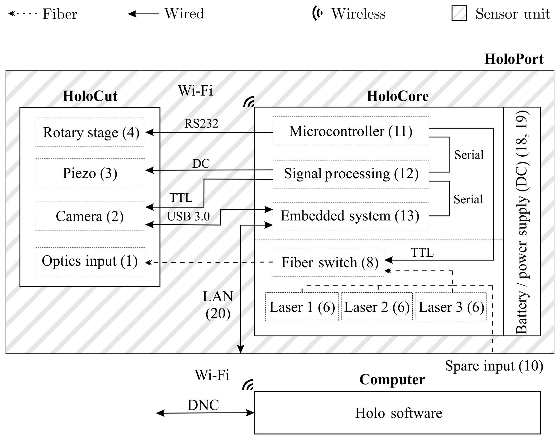
Figure 1System architecture: equipped with the control module, the wired sensor head HoloCut becomes the fully integrated measuring system HoloPort and operates completely wirelessly. The label numbers used in this figure also correspond to the numbers used Figs. 2a, b and 3a.
Featuring a simultaneous high measurement speed and accuracy, digital holography has become a versatile tool for complete 3-D inline quality control in industry (Fratz et al., 2017). The origins of digital holography date back to the 1950s (Gabór, 1948). However, only the development of electronic sensors (Goodman and Lawrence, 1967) and increasing computational power, such as that provided by graphics processing units (GPUs), has enabled the use of digital holography for industrial purposes (Schnars and Jüptner, 1994; Kuwamura and Yamaguchi, 1997; Carl et al., 2009; Fratz and Carl, 2014; Bove et al., 2005; Masuda et al., 2006; Kolenovic et al., 2003). With the introduction of small, powerful computing units originally developed for autonomous driving, a fully integrated wireless measuring system becomes possible.
This contribution presents the first wireless interferometer that allows a 3-D surface measurement of freshly machined components directly inside machine tools. In order to be capable of measuring optically rough technical surfaces, the sensor system works based on the principle of multiwavelength digital holography and achieves accuracies in the sub-micrometer range. It features a multiwavelength interferometer with three stabilized single mode, single frequency laser sources and a miniaturized GPU – all fully integrated in a compact housing and allowing wireless operation.
Integrating a surface-measuring optical sensor into a machine tool poses a number of challenges. First, the sensor has to withstand the harsh environmental conditions. Second the transmission of energy and data is a challenge: tool holders are currently not prepared for either of them. The development of such standardized interfaces has been in progress for several years, but none are currently in use (Komet Group GmbH, 2017). Thus, commercially available tactile sensors work wirelessly and are battery powered. In order to make the measuring system accessible for all machine tools, the standard interface according to DIN 69893 was chosen. Therefore, all electronics necessary for the operation of the sensor had to be integrated into the measuring system.
In Figs. 1–3, the components of the measuring system will be introduced. The numbers given in the figures correspond to the same objects in each figure.
Figure 1 depicts the system architecture: the sensor system HoloPort consists of the optical sensor head HoloCut and an integrated control system. The optical design of HoloCut (Seyler et al., 2017a) is based on the industrially proven HoloTop sensor (Fratz et al., 2017). With a focus on the form factor, the height of a standard tool was set as the mechanical boundary condition for the mechanical design. A 3-D folded beam path, as shown in Fig. 2a and b, leads to a miniaturized sensor and enables mounting in the center of gravity. The sensor head itself has a size of mm3 and weighs 7.5 kg. For further details regarding the optical and mechanical design, please refer to our previous publication (Seyler et al., 2017b).

Figure 2Sketch of the HoloCut sensor head bottom plane (a) and top plane (b) with interfaces to the control unit: camera (2), piezo actuator (3) and rotary stage (4). The machine integration in the center of gravity of the sensor (0) is realized by a 3-D layout of the optical beam path. (c) Finite methods natural frequency simulation of the HoloCut housing: the first eigenfrequency, shown here, is at 323 Hz and well above the frequencies occurring in machine tools (<300 Hz).
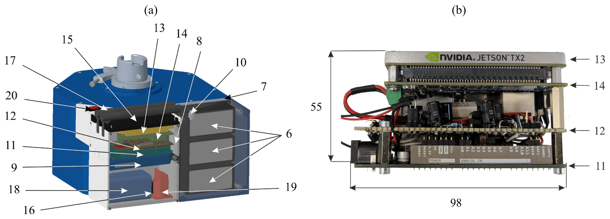
Figure 3(a) CAD model of the integrated control system including a battery powered (18) embedded architecture (11–14) and a fiber switch (8) toggling a three-laser system (6). (b) Detailed photograph of the embedded system.
At least three temporally phase-shifted interferograms (Cai et al., 2004) are recorded with a 9 MP (megapixel) camera (2), corresponding to a lateral sampling of approximately 7 µm × 7 µm and a field of view of 20 mm × 20 mm. Phase shifts are introduced by a piezo actuator (3). An integrated rotary motor (4a) with mounted half-wave plate and controller (4b) allows for the manipulation of the light distribution between reference and object light; thus, the sensor can be adapted to different surface conditions. A reference target (5) in the object beam path allows for absolute measurements and stitching of single measurements using encoder information of the machine tool.
The control system has been miniaturized and directly integrated into the sensor head. Figure 3a shows a computer-aided design (CAD) model of the complete measuring system HoloPort. The intended field of application of the sensor is the inspection of technical surfaces. Due to the roughness of such surfaces, unambiguous measurement ranges of at least a few micrometers are required. To achieve this, multiple lasers are used to record interferograms at different wavelengths (Wagner et al., 2000). From these interferograms the complex wavefront for each wavelengths is calculated, i.e., the amplitude and phase for each camera pixel. The combination of these complex wavefronts enable the numerical generation of phase images at so-called “synthetic” wavelengths, which correspond to the beat frequencies. The wavelength difference determines the unambiguous height measurement range: the smaller the difference, the larger the synthetic wavelength and the unambiguous measurement range. Large measurement ranges result in less accurate measurements. The combination of more than two wavelengths allows for cascading measurement ranges, and thus increases the ratio of measurement range and accuracy (Fratz et al., 2017).
Three 15–30 mW lasers (6) with wavelengths close to 632, 633 and 640 nm, respectively, are mounted on an aluminum block (7) and thermally insulated (8). A fiber switch (9) sequentially couples (1) these lasers to the sensor head. The system runs with different laser wavelengths and provides an additional external laser input (10). The results shown in this paper were achieved using synthetic wavelengths from 60 to 88 µm. The extension of the unambiguous measurement range up to several millimeters has already been shown using additional lasers (Carl et al., 2009) or specialized algorithms (Seyler et al., 2018b).
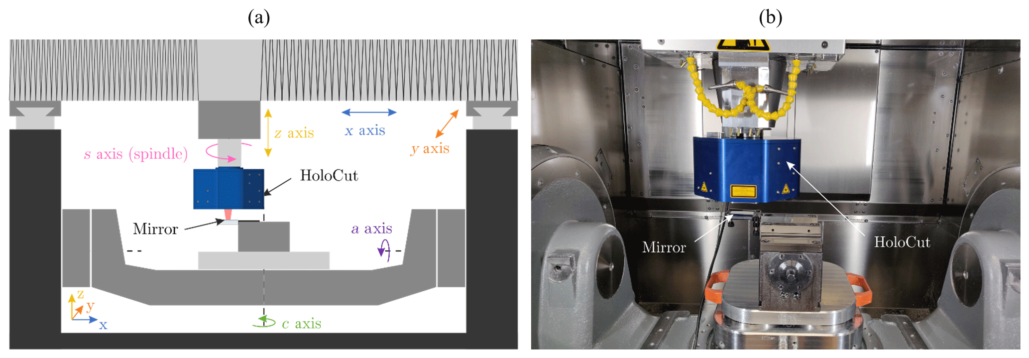
Figure 4(a) Schematic sketch of the machine tool with its moving axes and integrated HoloCut sensor head measuring in the z direction. (b) Photograph of the real setup.
A microcontroller (11) controls the previously described components. A specially designed circuit board (12) handles energy supply and signal distribution. Besides accuracy, the speed of a sensor system decisively determines the economic efficiency and benefits in the machine tool. HoloPort uses a fully integrated, powerful computing unit compatible with the CUDA (Compute Unified Device Architecture) programming interface: a Jetson TX2 board (13) and its carrier board (14) coupled to a separate heat sink (15) allow not only wired (16)/wireless data transfer (17) according to the state of the art but also data reduction inside the sensor itself. The resulting camera data of up to 270 MB per measurement are preprocessed internally and, thus, reduced by half – a processing time of less than 3 s is achieved for 9 million sample points. The pure measuring time is less than 1 s.
In addition, the computing power allows for in situ quality control of the acquired raw data. Interferograms disturbed by vibrations are internally evaluated for sufficient interference contrast (Seyler et al., 2018c) even before the wireless data transmission takes place. The power consumption of the whole system is approximately 20 W. A 5.2 Ah battery (18) can support the system for up to 7 h. The battery is fully charged within 75 min via a magnetic connector (19) and can be powered on by a mechanical switch (20).
After presenting the basic functionality and structure of HoloPort, the integration and characterization of the machine tool and the measuring system will be discussed in the following section.
3.1 Vibration analysis
As an interferometric measurement principle, digital holography is very susceptible to vibrations. Therefore, the stiffness and natural frequencies of the carrier system with the installed HoloCut sensor head were first analyzed in the machine tool. For this purpose, HoloCut was operated as a classic interferometer with a reduced field of view. Interference fringes were recorded against a mirror that was placed in the machining volume. Using a rectangular camera ROI (region of interest) of only 15 lines lead to a sampling rate of 1515 Hz, allowing for the analysis of frequencies beyond 750 Hz according to the Nyquist theorem. The sketch shown in Fig. 4a depicts the machine tool with its moving axes and integrated HoloCut sensor head measuring in the z direction. Figure 4b shows a photograph of the real setup.
First, the machine tool runs in normal operating mode but with disabled spindle control. Figure 5a shows the resulting vibration measurement in the z direction. With a typical relative movement of ∼50 nm, vibrations that occur are approximately 1 order of magnitude smaller than the illumination wavelength at 633 nm. At an exemplary exposure time of 1 ms they lead to a reduction of the interference contrast of only 1.1 %. The occurring vibration at a frequency of 84 Hz results in a maximum axial movement of 26 nm during this exposure time – this movement can be reduced by lower exposure times or increased laser power. Resultant effects have already been examined by Schiller et al. (2017) and are superimposed by movements between the image acquisitions. As shown in Fig. 5 for the machine tool in emergency stop mode, the vibration amplitude reaches only half of the previous value. The previously dominant frequency of 90 Hz has now completely disappeared. As all controls are deactivated in emergency stop mode, it can be assumed that this is the frequency of the machine axis control. Once the machine tool is completely turned off, the vibrations are again reduced by approximately 50 % in amplitude. The occurring frequencies are hardly affected at all.
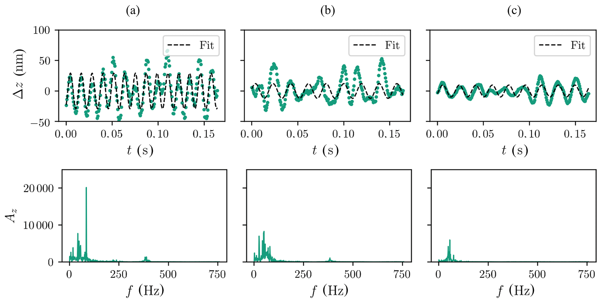
Figure 5Vibrations in different operational modes: (a) dominant control loop frequency of 90 Hz in operational mode, (b) reduced vibrations in emergency stop mode and (c) further reduced vibrations when the machine is turned off. Green lines correspond to the measured values; dashed black lines show the best-fit sinusoidal function.
In addition to these measurements, a confocal sensor and acceleration sensors were used to characterize the highly dynamic spindle control and vibrations in the x and y directions with equivalent results. Only the control loop of the spindle seems to have a noticeable negative effect on the measurement accuracy with HoloPort. Enabled spindle control results in a torsional vibration, leading to micrometer displacements perpendicular to the spindle axis. However, as the sensor should not rotate at all, this control loop is not necessary and can be deactivated during measurement.
In general, displacements that occur can be addressed by a combination of lateral and axial vibration compensation (Seyler et al., 2018c, 2019).
3.2 Performance
In order to characterize the performance differences in the measurement evaluation between the embedded system and the external measuring computer, a platform-independent software was developed which automatically performs a sequence of calculations with different parameters such as number of lasers and phase steps on a data set with typical filter operations and a resolution of 3008 pixels × 3008 pixels. For each combination, 120 measured values are recorded and then reduced to the respective mean value and standard deviation. Figure 6 shows these values for both processing strategies: the transmission of raw data with subsequent external data evaluation and internal data evaluation with reduced transmission.
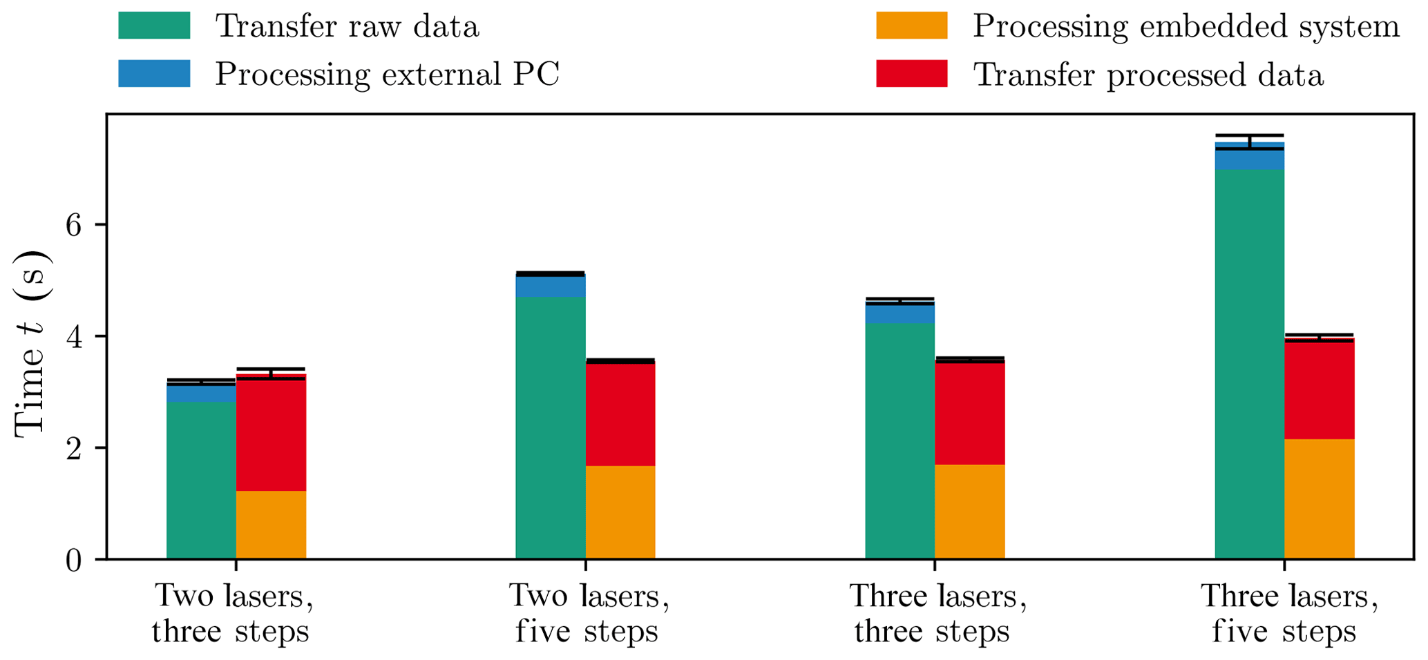
Figure 6Comparison of transmission of raw data (green) with external data evaluation (blue) to internal data evaluation (orange) with reduced data transmission (red). The latter configuration pays off with at least three lasers and/or five phase steps.
It turns out that internal data processing with three or more lasers or a minimum of five phase steps provides speed advantages. For three lasers and five phase steps, the amount of data before transmission can be reduced by a factor of 4, so that the total evaluation time drops from almost 8 s to about 4 s. The data processing time can be reduced by a factor of 2. The measured transmission time is significantly longer than expected. A theoretical transmission time of 0.7 s was expected for the processed data. The measured transmission time of the measured data, however, is 2.5 s on average, which is clearly above the calculated value. This can be caused by the low transmission speed at the beginning of the transmission and interference, e.g., from other Wi-Fi networks. The pure measurement speed of the system is independent of the evaluation and is far below 1 s; thus, in wired operation, a total measurement time including evaluation of about 1 s is achieved.
HoloPort has a maximum power consumption of 40 W, and the typical measured energy requirement is 20 W. Therefore, the choice of the evaluation strategy has an influence on the battery life. It turns out that with internal data processing more measurements can be carried out within one battery charge (4072 compared with 3533), but the battery is discharged earlier (388 min compared with 416 min). The battery life is up to 7 h, and charging the completely discharged battery takes about 75 min. As the Jetson systems offer various performance modes, even longer battery life seems realistic with intelligent performance control.
3.3 Temperature stability
High demands are placed on the measuring system for metrological operation in a machine tool. In production environments, the ambient temperatures differ by several degrees Celsius even in stationary operation of a machine tool, depending on the installation location. The temperature in the machine is determined by the type and height of the thermal load (travel speed, spindle speed, etc.). Temperature differences of up to 10 ∘C in the tool chamber are quite realistic (Weck and Brecher, 2006a).
Therefore, in addition to the internal temperature control of each individual laser, the laser system was thermally connected to the measuring head (as introduced in Sect. 2) and isolated from the rest of the electronics. Figure 7 shows the temperature curve of HoloPort under full load with lasers switched off and a more or less constant ambient temperature of 23 ∘C.
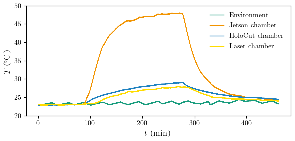
Figure 7Temperature curve of HoloPort at 23 ∘C ambient temperature: the isolation of the laser chamber from the Jetson chamber fulfills its purpose and leads to 20 ∘C less heating.
In this scenario, the heat input of the evaluation electronics (Jetson chamber) and the camera to the laser chamber can be observed. The latter only sees a small part of the high heat development of the evaluation electronics; thus, the lasers only heat up by about 5 ∘C, whereas the chamber of the evaluation electronics heats up by about 25 ∘C to almost 50 ∘C. It is remarkable that the laser chamber faces lower heat input than the measuring head itself, which is only heated by the <4.5 W heat input of the camera. Due to the interferometric measuring principle, slowly drifting temperatures of the HoloCut housing are not critical for the measurement of a single measuring field and only play a role in measurements with absolute references. In addition, the sensor head responds very slowly to external temperature fluctuations due to its large thermal mass. The Jetson internal temperature sensor shows a temperature of 30 ∘C without load, which increases to 70 ∘C under load. All observed temperatures are within the permissible operating temperatures of the individual components.
In general, there are two classes of manufactured surfaces in milling: engineered surfaces and non-engineered surfaces. Engineered surfaces such as bearings and seals are generally manufactured to provide functional properties or are subject to special safety requirements (Stout and Blunt, 2001).
Figure 8 shows the inspection of a typical non-engineered milling surface in a Hermle C32U 5-axis milling machine. HoloPort easily resolves the milling structure of the surface, revealing height differences h between individual milling paths of up to 10 µm. A cross section of 10 individual measurements at the same position illustrates the repeatability in the sub-micrometer range. With a measuring field of up to 20 mm × 20 mm at 9 million sample points, irregularities within the microstructure as well as machine faults quickly become apparent. In contrast to the tactile state-of-the-art sensors, the system cannot only resolve longwave components but also shortwave structures and defects of the milling operation. Due to the inherent morphological filtering of the probe head, tactile sensors, in principle, cannot detect these characteristics. The benefit of the measuring system in the optimization of milling parameters quickly becomes obvious at this point.
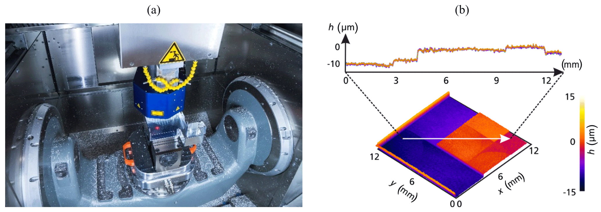
Figure 8(a) Inspection of a typical milling surface by HoloPort inside a Hermle C32U 5-axis milling machine at Fraunhofer IPM. (b) Measured height differences h between milling paths of a typical milled part in the range of 10 µm. A cross section of 10 individual measurements at the same position demonstrates the measuring repeatability.
For comparison to white-light, interferometric and confocal laboratory reference 3-D measuring devices, surface parameters according to ISO 25178 were previously evaluated: all three measuring methods deliver comparable results and are able to detect both an increasing roughness of the surface due to wear of the milling cutter and a machine error (Seyler et al., 2018d).
Not only the analysis of surface parameters, but also the extensive measurement of different inspection parameters represent applications for quality monitoring (Schiller et al., 2017). Figure 9 shows a milled laser heat sink with mapped surface measurement.
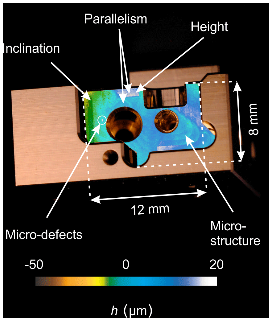
Figure 9HoloPort maps the component surface in a fraction of a second with micrometer accuracy directly in the machine tool (as in the example of a heat sink for laser assembly). Alongside the geometry, relevant surface parameters such as micro-defects and microstructures as well as the height, parallelism and inclination of surfaces can be measured simultaneously.
The full-field measurement shows the surface quality and additionally allows for the quantitative extraction of geometrical parameters: micro-defects and microstructures as well as the height, parallelism and inclination of surfaces can be evaluated based on the gathered measurement data.
Using the dynamic numerical control (DNC) interface of the machine tool, axis positions can be read out and used for a CAD comparison – the system becomes a full-field CMM. Even complex work pieces can be inspected completely and directly within the machine for the first time (Seyler et al., 2018a). The accuracy of a complete point cloud of the surface is limited by the accuracy of the machine tool axes, which is typically in the single micrometer range.
Further test measurements of a complex formed milling part have been carried out to demonstrate feasibility of quality inspection directly in the machine tool instead of using an additional CMM situated within a temperature-controlled measurement room. The combination of more than 30 measurements for flatness determination has been carried out with an extension of 100 mm × 60 mm, which corresponds to almost 300 million data points. Evaluation of the combined data set shows flatness information within the single micrometer range. The determination of lateral distances between reference marks located on the measured surface in the range of the lateral sampling of the sensor at 7 µm appears realistic.
For additional application examples and measurement results please refer to Seyler et al. (2017a), Seyler et al. (2018a, b, c, d), Seyler (2019) and Seyler and Engler (2019).
An optical sensor measuring the surface integrity with a large field of view directly inside the machine tool opens up new possibilities for process control and optimization (Luo and Qin, 2018).
The feedback of the measurement results into the manufacturing process is a key point, especially in hybrid manufacturing. As the Jetson module was originally developed for autonomous driving purposes, the system is also capable of machine learning analyses.
Furthermore, the system is prepared for use on CMM and robots – the possibilities and limits will be determined in future studies. In addition, the measuring system will be further miniaturized to be compatible with standard tool changers.
Digital holography has even been proven to work on moving objects at speeds of several millimeters per second – simplified handling becomes possible for inline inspection, which, in turn, allows for faster production control (Schiller et al., 2017). The limits of a scanning sensor in a multiaxial system will be analyzed in future experiments.
Online measurements of surface integrity in machined production have been motivated. Digital holography meets the requirements for measurement accuracy in the micrometer range at simultaneous high measurement speed.
A new digital holographic sensor system for 3-D surface measurements inside a machine tool has been presented and characterized. It features 9 million 3-D samples and, to our knowledge, it is the first time that micrometer precision of such a system on an area of up to 20 mm × 20 mm has been demonstrated with various milled samples. Due to the short processing time of 3 s (pure measuring time of less than 1 s), closed-loop quality control directly inside the machine tool is feasible for the first time.
Further investigations of the detection and compensation of vibrations will be carried out in the future.
Data were been submitted on 28 January 2020: https://doi.org/10.24406/fordatis/51 (Seyler et al., 2020).
TS was responsible for the methodology, conceptualization, data curation, investigation, software, visualization, the project administration and writing the paper; JE contributed to the conceptualization and software; TB contributed to the methodology, conceptualization and software; MF was responsible for the methodology, conceptualization, funding acquisition and project administration; AB contributed to funding acquisition and supervision; and DC was responsible for funding acquisition and supervision.
The authors declare that they have no conflict of interest.
This article is part of the special issue “Sensors and Measurement Systems 2019”. It is a result of the “Sensoren und Messsysteme 2019, 20. ITG-/GMA-Fachtagung”, Nuremberg, Germany, 25–26 June 2019.
We would like to thank the Baden-Württemberg Stiftung gGmbH for their financial support regarding the development of the HoloCut sensor. We appreciate the support and good cooperation from Hermle AG that was given during the integration of the measurement system.
This paper was edited by Jürgen Czarske and reviewed by three anonymous referees.
Bove, J. V. M., Plesniak, W. J., Quentmeyer, T., and Barabas, J.: Real-time holographic video images with commodity PC hardware, in: Stereoscopic Displays and Virtual Reality Systems XII, San Diego, 255–262, 2005.
Cai, L. Z., Liu, Q., and Yang, X. L.: Generalized phase-shifting interferometry with arbitrary unknown phase steps for diffraction objects, Opt. Lett., 29, 183–185, https://doi.org/10.1364/OL.29.000183, 2004.
Carl, D., Fratz, M., Pfeifer, M., Giel, D. M., and Höfler, H.: Multiwavelength digital holography with autocalibration of phase shifts and artificial wavelengths, Appl. Optics, 48, H1–H8, 2009.
Fratz, M. and Carl, D.: Novel Industry Ready Sensors for Shape Measurement Based on Multi Wavelength Digital Holography, in: Fringe 2013: 7th nternational Workshop on Advanced Optical Imaging and Metrology, edited by: Osten, W., Springer, Berlin, Heidelberg, 479–484, https://doi.org/10.1007/978-3-642-36359-7_84, 2014.
Fratz, M., Beckmann, T., Schiller, A., Seyler, T., Bertz, A., Carl, D., and Buse, K.: Digital Holography: Evolution from a Research Topic to a Versatile Tool for the Inline 100 % 3D Quality Control in Industry, in: AMA Conferences 2017 – SENSOR 2017 and IRS2 2017, 30 May–1 June 2017, Nürnberg, Germany, 286–289, available at: https://www.ama-science.org/proceedings/details/2580 (last access: January 2020), 2017.
Gabór, D.: A New Microscopic Principle, Nature, 161, 777–778, https://doi.org/10.1038/161777a0, 1948.
Goodman, J. W. and Lawrence, R. W.: Digital Image Formation From Electronically Detected Holograms, J. Opt. Soc. Am., 11, 77–79, https://doi.org/10.1063/1.1755043, 1967.
Jiang, X. J., Gao, F., Martin, H., Williamson, J., and Li, D.: On-Machine Metrology for Hybrid Machining, in: Hybrid Machining: Theory, Methods, and Case Studies, edited by: Luo, X. and Qin, Y., Elsevier Science & Technology, San Diego, 2018.
Knauer, M. C., Richter, C., and Häusler, G.: 3D sensor zoo – Species and natural habitats, Laser Tech. J., 3, 33–37, https://doi.org/10.1002/latj.200790081, 2006.
Kolenovic, E., Osten, W., Klattenhoff, R., Lai, S., von Kopylow, C., and Jüptner, W.: Miniaturized digital holography sensor for distal three-dimensional endoscopy, Appl. Optics, 42, 5167–5172, https://doi.org/10.1364/ao.42.005167, 2003.
Komet Group GmbH: Bauteilgerechte Maschinenkonfiguration in der Fertigung durch Cyber-Physische Zusatzmodule: BaZMod, available at: https://www.bazmod.de/img/FuE-Abschlussbericht_BaZMod.pdf (last access: January 2020), 2017.
Kuwamura, S. and Yamaguchi, I.: Wavelength scanning profilometry for real-time surface shape measurement, Appl. Optics, 36, 4473, https://doi.org/10.1364/AO.36.004473, 1997.
Luo, X. and Qin, Y. (Eds.): Hybrid Machining: Theory, Methods, and Case Studies, Elsevier Science & Technology, San Diego, 2018.
Masuda, N., Ito, T., Tanaka, T., Shiraki, A., and Sugie, T.: Computer generated holography using a graphics processing unit, Opt. Express, 14, 603–608, https://doi.org/10.1364/OPEX.14.000603, 2006.
Schiller, A., Beckmann, T., Fratz, M., Belzer, D., Bertz, A., Carl, D., and Buse, K.: Digital holography on moving objects: interference contrast as a function of velocity and aperture width, Appl. Optics, 56, 4622–4628, https://doi.org/10.1364/AO.56.004622, 2017.
Schnars, U. and Jüptner, W.: Direct recording of holograms by a CCD target and numerical reconstruction, Appl. Optics, 33, 179–181, https://doi.org/10.1364/AO.33.000179, 1994.
Seyler, T.: HoloPort – 3D-Inline-Messtechnik für die Werkzeugmaschine, wt Werkstattstechnik online, 109, 319–320, 2019.
Seyler, T. and Engler, J.: HoloPort – 3D-Sensor for machine tools, in: 20. GMA/ITG-Fachtagung Sensoren und Messsysteme 2019, edited by: AMA Verband für Sensorik und Messtechnik e.V., Nürnberg, 43–49, https://doi.org/10.5162/sensoren2019/1.1.2, 2019.
Seyler, T., Fratz, M., Beckmann, T., Bertz, A., and Carl, D.: 3D-Prüfung von Präzisionsoberflächen: Qualitätssicherung – submikrometergenau im Sekundentakt, WOMAG, available at: https://www.wotech-technical-media.de/womag/ausgabe/2017/09/D03_deburring_seyler_09j2017/D03_deburring_seyler_09j2017.php (last access: January 2020), 2017a.
Seyler, T., Fratz, M., Beckmann, T., Bertz, A., and Carl, D.: Miniaturized multiwavelength digital holography sensor for extensive in-machine tool measurement, Proc. SPIE, 10329, F1–F12, https://doi.org/10.1117/12.2270087, 2017b.
Seyler, T., Fratz, M., Grün, V., and Börret, R.: Flächige 3D-Messung in der Werkzeugmaschine, Maschinenmarkt, 10–12, available at: https://www.maschinenmarkt.vogel.de/flaechige-3d-messung-in-der-werkzeugmaschine-a-718625/ (last access: January 2020), 2018a.
Seyler, T., Fratz, M., Beckmann, T., Schiller, A., Bertz, A., and Carl, D.: Extending the Depth of Field beyond Geometrical Imaging Limitations Using Phase Noise as a Focus Measure in Multiwavelength Digital Holography, Appl. Sci., 8, 1042, https://doi.org/10.3390/app8071042, 2018b.
Seyler, T., Fratz, M., Beckmann, T., Bertz, A., Carl, D., Grün, V., Börret, R., Ströer, F., and Seewig, J.: Extensive microstructural quality control inside a machine tool using multiwavelength digital holography, in: VII International Conference on Speckle Metrology, Janów Podlaski, Poland, https://doi.org/10.09.2018-12.09.2018, 2018c.
Seyler, T., Fratz, M., Grün, V., Börret, R., Ströer, F., and Seewig, J.: Messen am eingerichteten Werkstück, Qualität und Zuverlässigkeit, 63, 52–54, 2018d.
Seyler, T., Bienkowski, L., Beckmann, T., Fratz, M., Bertz, A., and Carl, D.: Multiwavelength digital holography in the presence of vibrations: laterally resolved multi-step phase-shift extraction, in: Digital Holography and Three-Dimensional Imaging 2019, Bordeaux, Tu4B.5, 2019.
Seyler, T., Engler, J., Beckmann, T., Fratz, M., Bertz, A., and Carl, D.: HoloPort – design and integration of a digital holographic 3-D sensor in machine tools: Supplementary Data, https://doi.org/10.24406/fordatis/51, 2020.
Stout, K. J. and Blunt, L.: A contribution to the debate on surface classifications – random, systematic, unstructured, structured and engineered, Int. J. Mach. Tools Manufact., 41, 2039–2044, https://doi.org/10.1016/S0890-6955(01)00069-4, 2001.
Wagner, C., Osten, W., and Seebacher, S.: Direct shape measurement by digital wavefront reconstruction and multiwavelength contouring, Opt. Eng., 39, 79–85, https://doi.org/10.1117/1.602338, 2000.
Weck, M. and Brecher, C.: Werkzeugmaschinen 3: Mechatronische Systeme, Vorschubantriebe, Prozessdiagnose, Springer, Berlin, Heidelberg, 2006a.
Weck, M. and Brecher, C.: Werkzeugmaschinen 4: Automatisierung von Maschinen und Anlagen, Springer, Berlin, Heidelberg, 2006b.