the Creative Commons Attribution 4.0 License.
the Creative Commons Attribution 4.0 License.
 | 21 Nov 2018
Comparison between different fiber coatings and adhesives on steel surfaces for distributed optical strain measurements based on Rayleigh backscattering
Martin Weisbrich
Klaus Holschemacher
Optical fiber measurement systems have recently gained popularity following a multitude of intensive investigations. A new technique has been developed for these measurement systems that uses Rayleigh backscatter to determine the distributed strain measurement over the total length of a fiber. These measurement systems have great potential in civil engineering and structural health monitoring.
This paper addresses some preliminary comparisons between three different fiber coatings and six different adhesives on steel structures. The results are based on a bending test with specimens made of precision flat steel; optical fiber strain measurements were compared with photogrammetric strain measurements.
Analysis of the test data showed a strong correlation between the optical measurement system's results and the theoretical results up to the yielding point of the steel. Furthermore, the results indicate that fibers with the Ormocer® and polyimide coatings have almost the same strain values as the reference measurement method.
The main results of this investigation are a guideline describing how to attach optical fibers to steel surfaces for distributed fiber optical strain measurements and recommendations for coatings to obtain realistic strain values. Additionally, the advantages of distributed strain measurements were revealed, which illustrates the potential of Rayleigh backscattering applications.


Intensive investigations in recent years have brought attention to the distributed optical strain measurement system (Czarske and Müller, 1994; Horiguchi et al., 1995; Parker et al., 1997). This system represents a modern and innovative method of measuring strain or temperature in the matrices and surfaces of building materials, especially in the structural health monitoring (SHM) field (Barrias et al., 2018; Inaudi and Glisic, 2005).
Distributed optical strain measurements have distinct advantages over established measurement techniques such as strain gauges. First, optical fiber methods are dielectric, corrosion resistant, and immune to electromagnetic fields (Samiec, 2012). Second, the measurements are distributed over the entire length of the measuring fiber and not at predefined points as in Fiber Bragg gratings (FBG; Weisbrich et al., 2017).
Three distributed optical fiber systems have emerged for SHM applications: Raman, Brillouin, and Rayleigh backscattering (Lopez-Higuera et al., 2011). While Raman scattering is only suitable for temperature measurements, Brillouin and Rayleigh scattering can be used to measure strain and temperature (Lopez-Higuera et al., 2011). The main differences between Brillouin and Rayleigh scattering are mainly the spatial resolution, fiber length, and accuracy. Brillouin scattering can measure over several kilometers with a spatial resolution in the meter range (Leung et al., 2015; Parker et al., 1997), whereas Rayleigh scattering has a spatial resolution of approximately 1 mm and is currently limited to a maximum length of 70 m (Samiec, 2012). Further investigations reveal that, with Brillouin backscattering, local resolutions in the centimeter range can be achieved with shorter fiber lengths (Song et al., 2010). It has also been demonstrated that Rayleigh backscattering can be used to measure in the kilometer range (Zhou et al., 2015).
Two important features directly influence strain propagation in reinforced steel. The first is the fiber coating, which is a sheathing that often consists of a polymer (e.g., acrylate, polyimide) or a metal (e.g., copper; Schilder et al., 2013). Depending on the material, slippage may occur between the fiber coating and the fiber cladding, which can distort the displayed strains. The second aspect is slippage that might occur between the fiber coating, adhesive, and substrate (Cheng et al., 2005). The functional properties of the adhesive, such as the strain transmission and long-term stability, are mainly determined by the preparation of the adhesive area and execution of the gluing process (Ebnesajjad and Landrock, 2014).
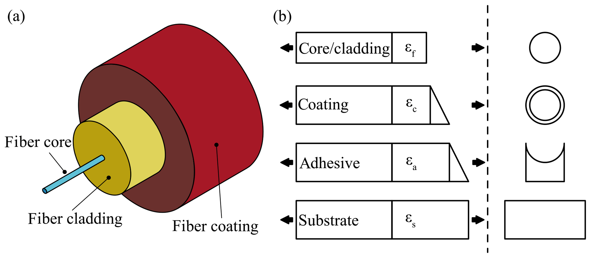
Figure 1(a) Structure of a fiber; (b) Slippage between fiber core and substrate based on Cheng et al. (2005).
Several research groups have investigated the influence of fiber coatings on strain transfer. Schilder et al. examined the strain transfer between polyimide and copper coatings on polymer surfaces (Schilder et al., 2013). Davis et al. (2016) and Quiertant et al. (2012) investigated a comparison between nylon- and polyimide-coated fibers on reinforcing bars. Hoult et al. studied the influence of polyimide and nylon fiber coatings on flat steel specimens (Hoult et al., 2014). Schlüter determined significantly higher strain differences of Ormocer and acrylate coatings on aluminum samples compared to the reference measurement than the investigations on steel samples presented here (Schlüter, 2010). Overall, these publications inadequately addressed the aspects of different coatings and adhesives as well as the preparation of the adhesive joint.
This study compares the influence of various coatings and adhesives on strain measurements to improve the application of distributed optical fiber sensors (DOFS) to steel bar reinforcements. For this purpose, three different polymer coatings with six different adhesives were investigated. A four-point bending test was used to evaluate the precision flat steel test specimens, and a photogrammetric strain measurement served as a reference method. The results show a high correlation between the reference method and the analytical design for two of the three examined fiber coatings.
2.1 Coating materials and adhesives
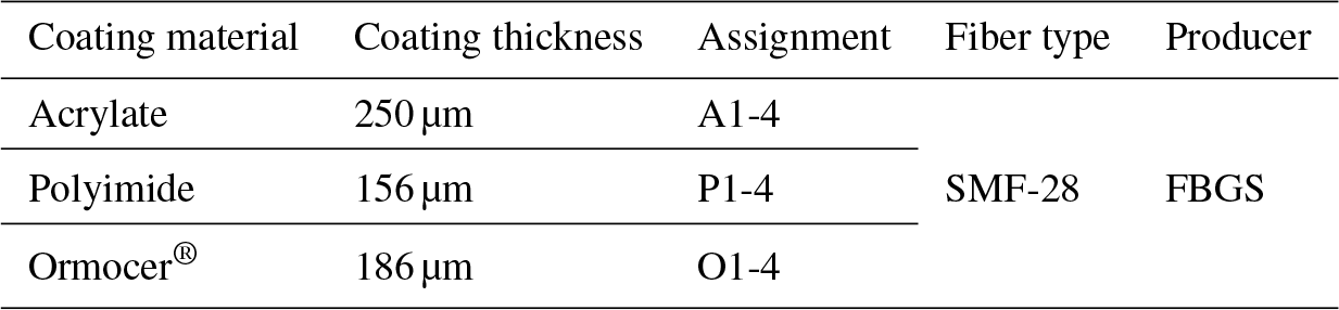
In this study, the Ormocer® coating was tested in addition to the polyimide and acrylate coating materials described in the literature (Schilder et al., 2013; Davis et al., 2016; Quiertant et al., 2012; Hoult et al., 2014). The standard Ormocer (organically modified ceramic) material was developed for FGB fibers and offers good strain transfer (FBGS International N.V., 2015).
To increase the significance of the test, four test specimens were prepared with the same coating material. Table 1 summarizes the distribution of the coating materials.
To analyze and compare the application of the fiber sensor, six adhesives composed of four adhesive types were used (Table 2). The DOFS system manufacturer recommends, among others, M-Bond 200 (Luna Inc., 2017), which was one of three cyanoacrylate adhesives tested in this study. Cyanoacrylate adhesives are often utilized for measurement applications (e.g., M-Bond 200, Z70). However, unlike Z70 and M-bond 200, Loctite 4902 is a highly elastic cyanoacrylate adhesive with an elongation at break greater than 120 % (Henkel Corporation, 2015). Brockmann determined that highly elastic systems can gradually rebuild connections dissolved by water (Brockmann et al., 2009). This observation is particularly interesting for fiber sensors used on reinforcing bars in moist concrete environments. Another way to protect the adhesive joint in the wet and alkaline environment of concrete is a two-component epoxy resin (Luna Inc., 2017); EA 3430 from Loctite was used for this purpose in this study. The advantages of a rapid-hardening cyanoacrylate in combination with the resistance of an epoxy resin are offered by the hybrid adhesive Loctite HY 4090. The methyl methacrylate MD Megabond 2000 also has good adhesive properties in damp, aggressive environments such as those found in concrete (Marston-Domsel GmbH, 2016).

2.2 Specimens, preparation, and application procedure
A precision flat steel S355J2+N with a yield strength of approximately 355 N mm−2 was used as the carrier material for the fiber sensors (DIN Deutsches Institut für Normung e.V., 2004). This material offers small geometric tolerances to ensure optimal comparability between specimens. The dimensions of the test specimens are mm, with tolerances in width and height of mm.
Prior to applying the fiber, the steel surfaces must be prepared for the application process (Ebnesajjad, 2010); this preparation procedure can also improve the long-term stability of the adhesive joint (Ebnesajjad, 2010; Brockmann, 1976). The manufacturer's recommendations were supplemented by a few steps, which led to the following preparation approach (Luna Inc., 2017):
-
basic cleaning of the surface;
-
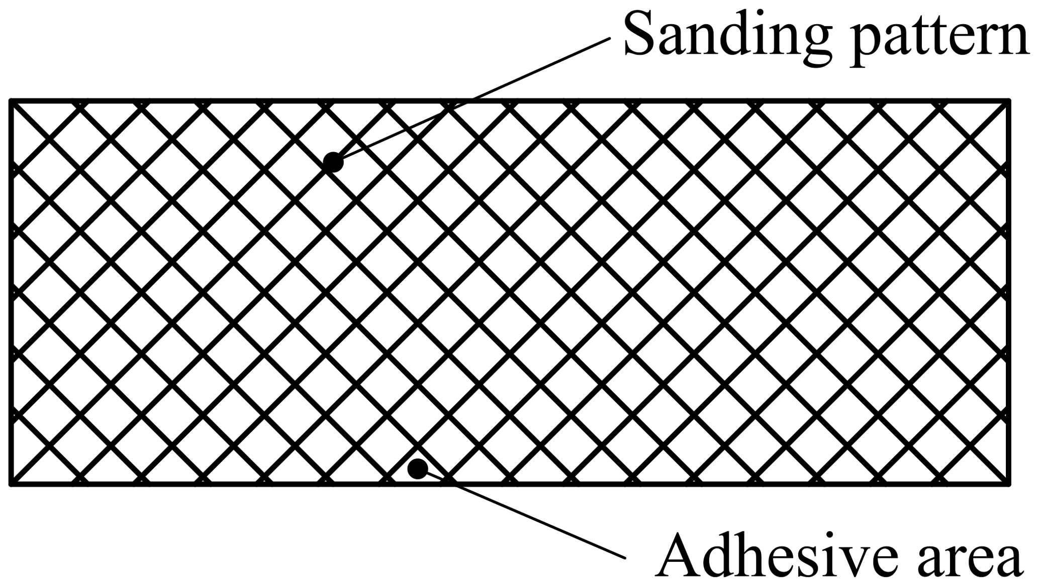
sanding the surface with 200 grit sandpaper, according to the pattern in Fig. 2;
-
blowing debris off the surface;
-
sanding the surface with 400 grit sandpaper, according to the pattern in Fig. 2;
-
blowing debris off the surface;
-
chemical cleaning of the surface with isopropanol;
-
pretreatment of the surface with primer (M-Bond 200);
-
chemical cleaning and prefixing the fiber.
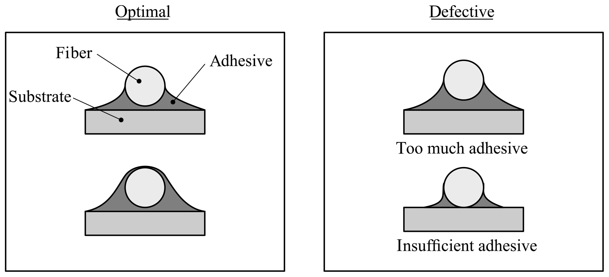
The quality of the adhesive joint is essential for the transmission of the strain from the specimen to the fiber. For this reason, this step must be performed with maximal accuracy. After preparing the surfaces and prefixing the fiber, the application procedure commenced. The adhesive was carefully applied with foam swabs to avoid having either excessive or insufficient adhesive on the steel surface (Luna Inc., 2017). Figure 3 shows cross sections of representative optimal and defective adhesive joints.
2.3 Test arrangement and procedure
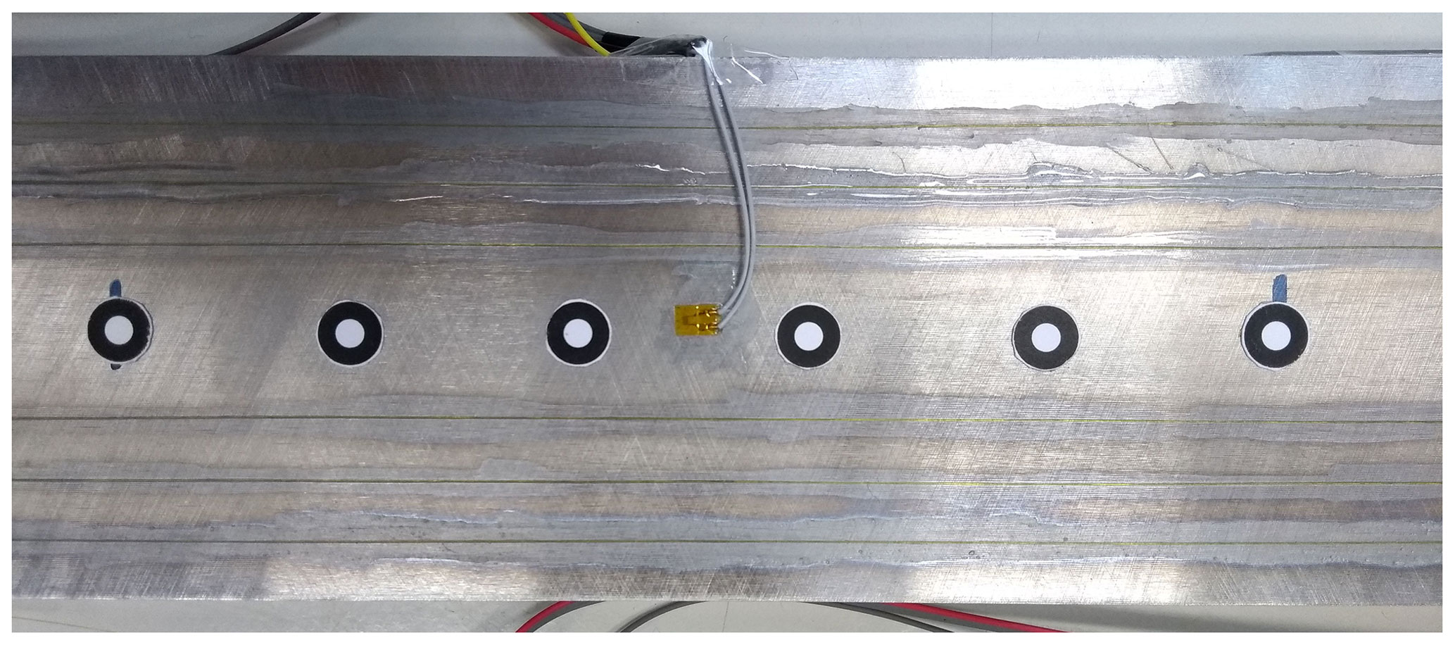
A four-point bending test was used to evaluate the specimens described in Sect. 2.2. The four-point bending test was chosen for this purpose, because it has some decisive advantages over the tensile test. Unlike the tensile test, specimens in a four-point bending test lay on the supports and are not clamped, which prevents the formation of offset moments. Another advantage compared to the tensile test is the lack of slippage on the supports. In previous studies, these disadvantages significantly distorted the results (Weisbrich et al., 2017). Figure 4 illustrates the test setup and arrangement of the fiber and reference measurement on the specimen. Six fiber strands were applied to each specimen using the adhesives listed in Table 2. For comparison, six marks were applied in the middle of the specimen for the photogrammetric reference measurement.
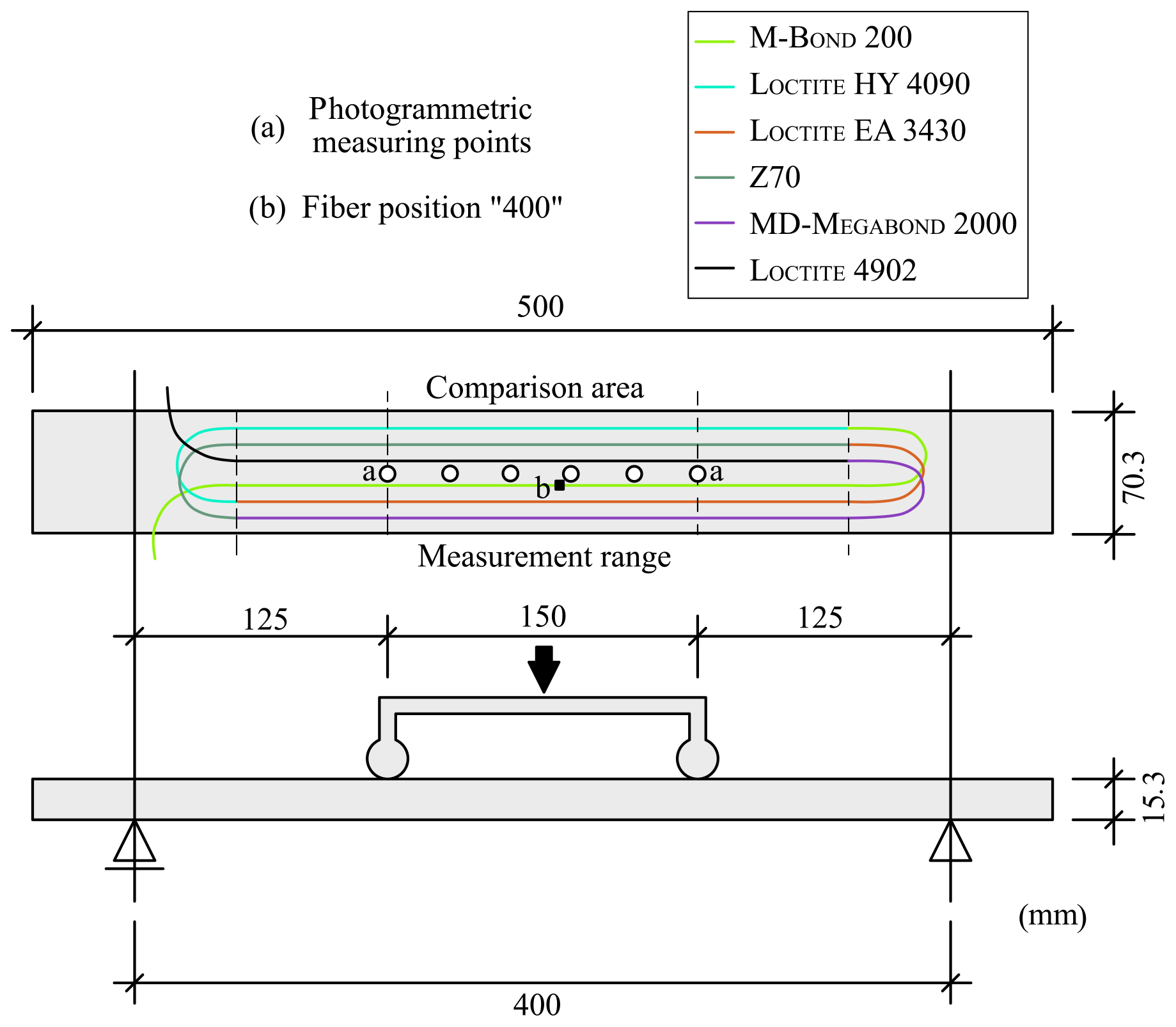
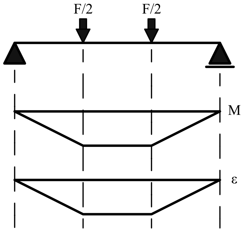
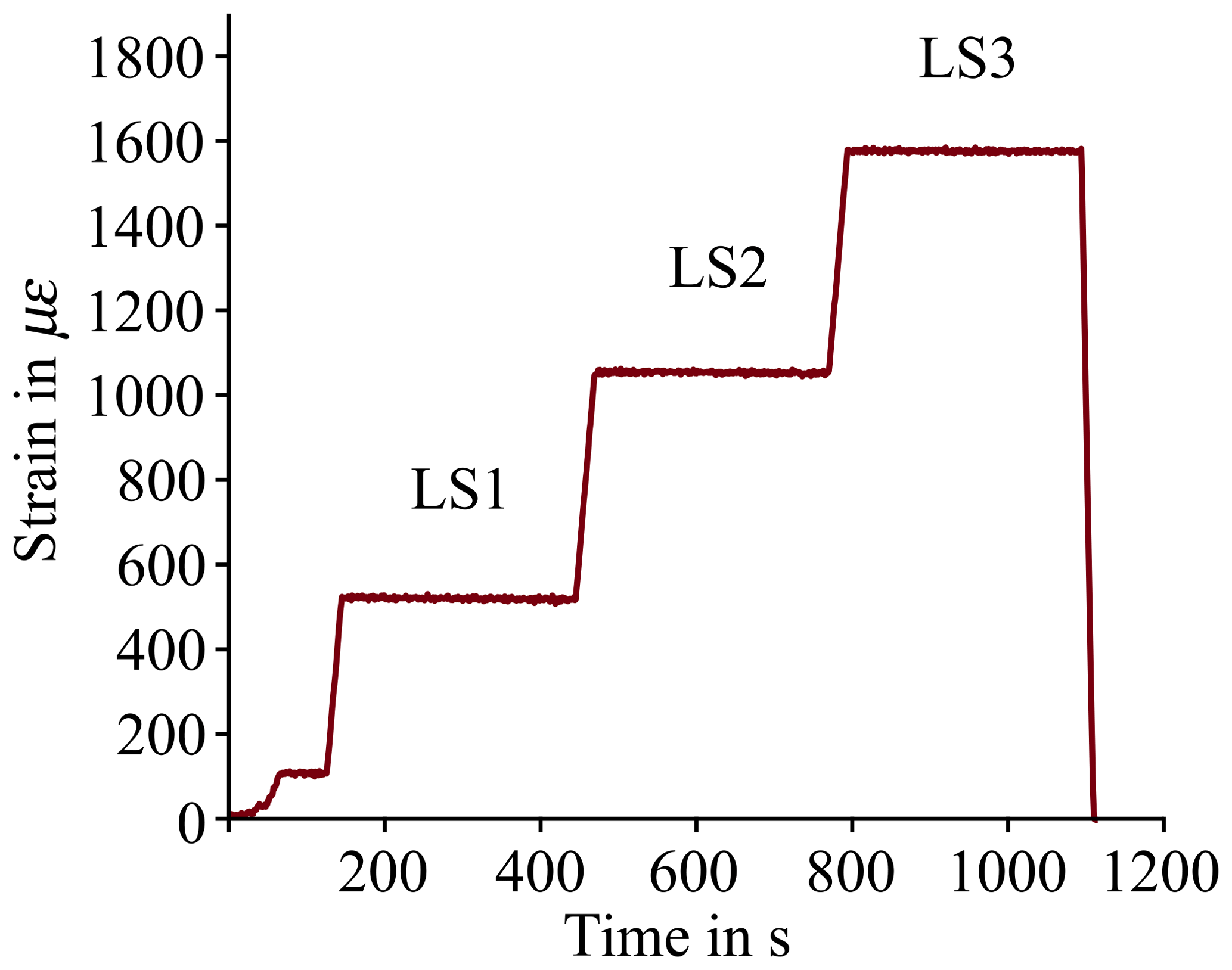
The four-point bending test is suitable for this type of comparison, as shown in the moment and strain curves in Fig. 5. There is a constant moment between the two load inputs that forms the comparison area (cf. Fig. 4). This constant moment leads to a constant strain curve (cf. Fig. 5).
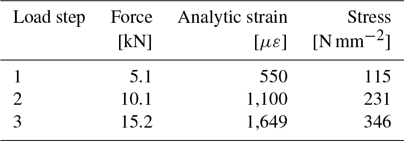
The test was carried out in three consecutive load steps at ambient temperature (Table 3). The load level was maintained for 5 min in each load step. A maximum load of 15.2 kN was chosen to reach approximately 98 % of the yield strength of the precision flat steel.
Table 3Load steps of the test and the calculated strain and stress of the specimen.
2.4 DOFS method and reference measurement
The interrogator ODiSI-B from Luna Inc. uses swept-wavelength interferometry to measure the Rayleigh backscattering as a function of the position in the optical fiber. The strain along the fiber can be determined from the frequency shift by using Fourier transformation. Several studies contain additional information about the physical and operating principles of DOFS based on Rayleigh backscattering (Samiec, 2012; Weisbrich et al., 2017; Gifford et al., 2005; Froggatt and Moore, 1998).
A point-tracking technique using photogrammetric cameras served as a reference measurement. This method uses a series of high-contrast, circular targets to detect the strain of the specimen. Further information on the reference method is presented by Baqersad et al. (2017).
2.5 Evaluation process
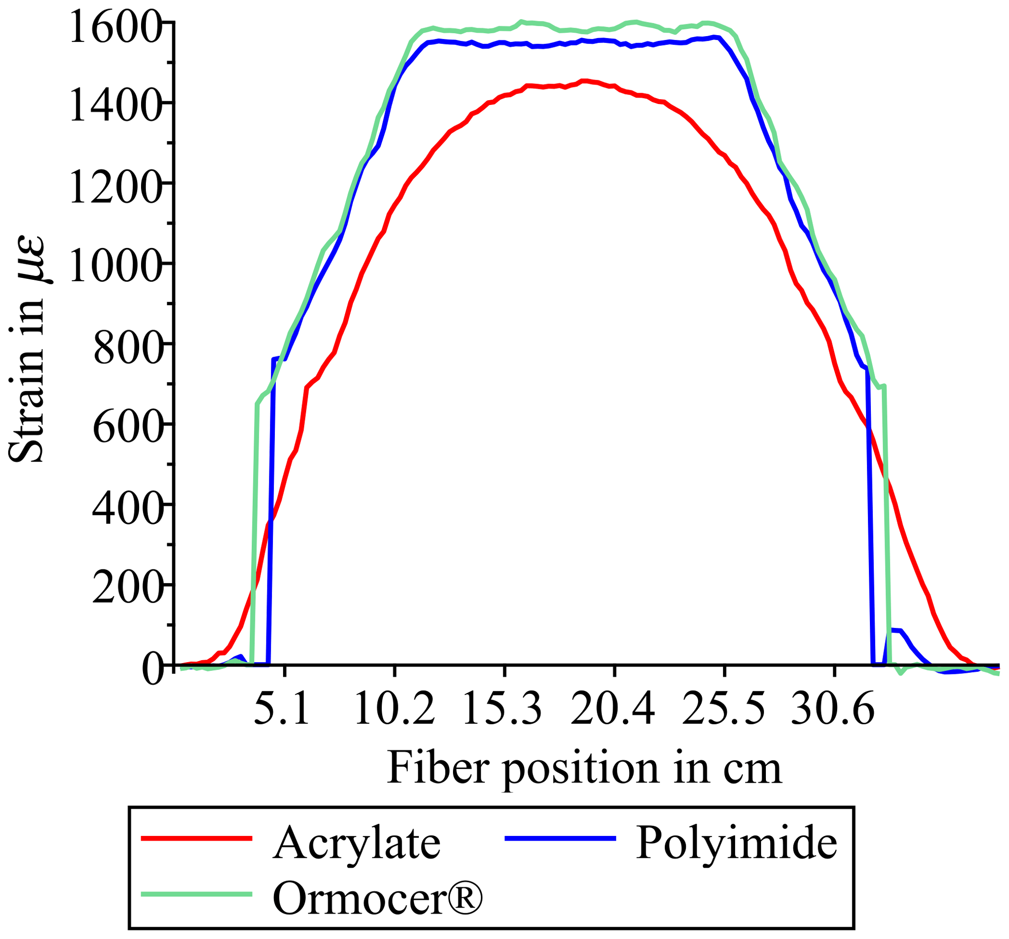
Distributed fiber optic strain measurements offer the possibility of showing many strain states of a specimen; there was a measuring point every 0.261 cm throughout the measurement range of the fiber. Accordingly, the entire measuring range of the fiber, including rounding at approximately 1300 measuring points, corresponds to 339 cm (see Fig. 7). Figure 7 shows the entire fiber at one point in time during the third load step. Furthermore, the figure illustrates the six fiber strands with their respective adhesives.
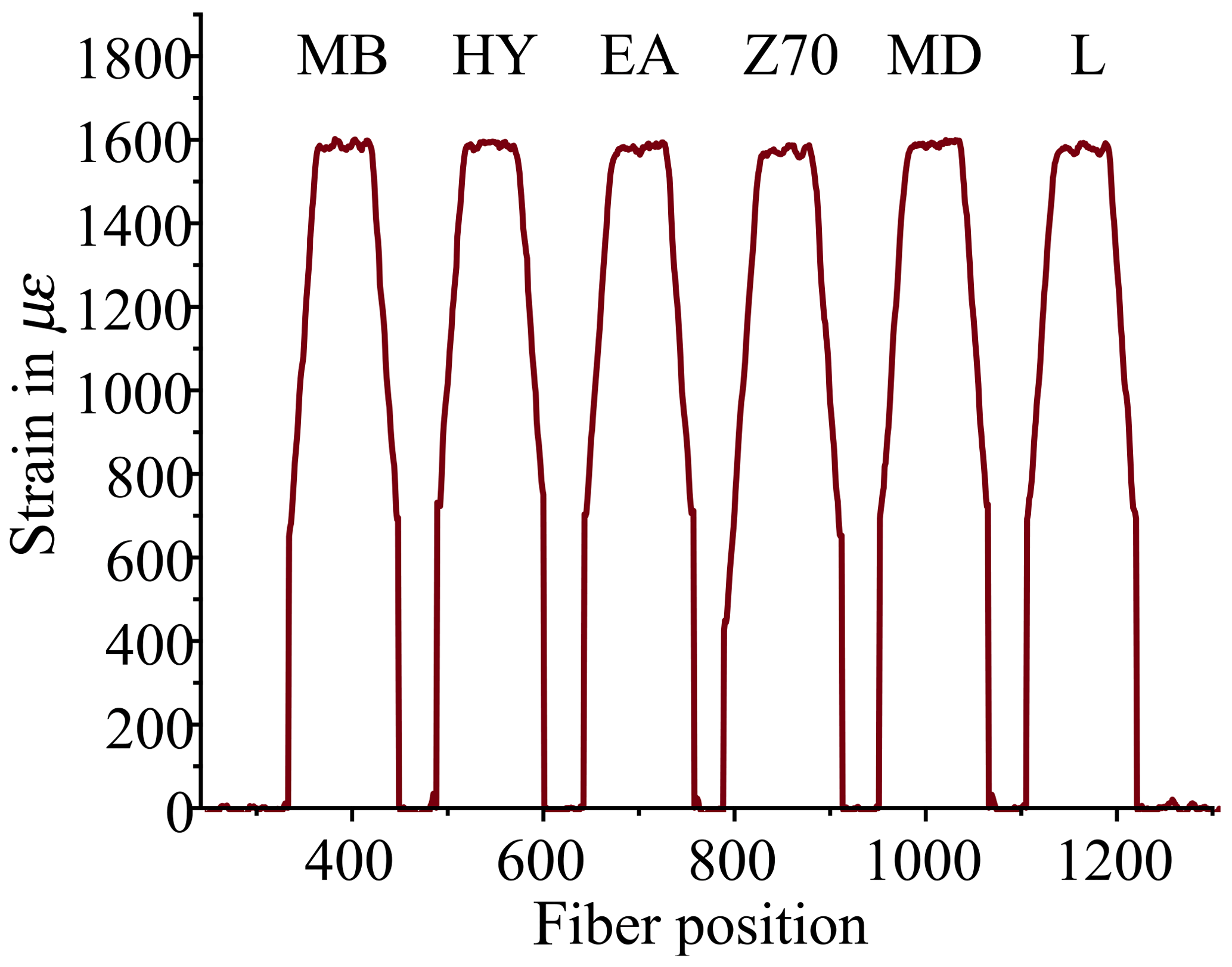
With a test duration of approximately 20 min and acquiring data at a frequency of 1 Hz, more than 1.56 million strain values were produced for a single fiber. Figure 8 shows the complete sequence of the test at the fiber position “400”, for example (see Fig. 4).
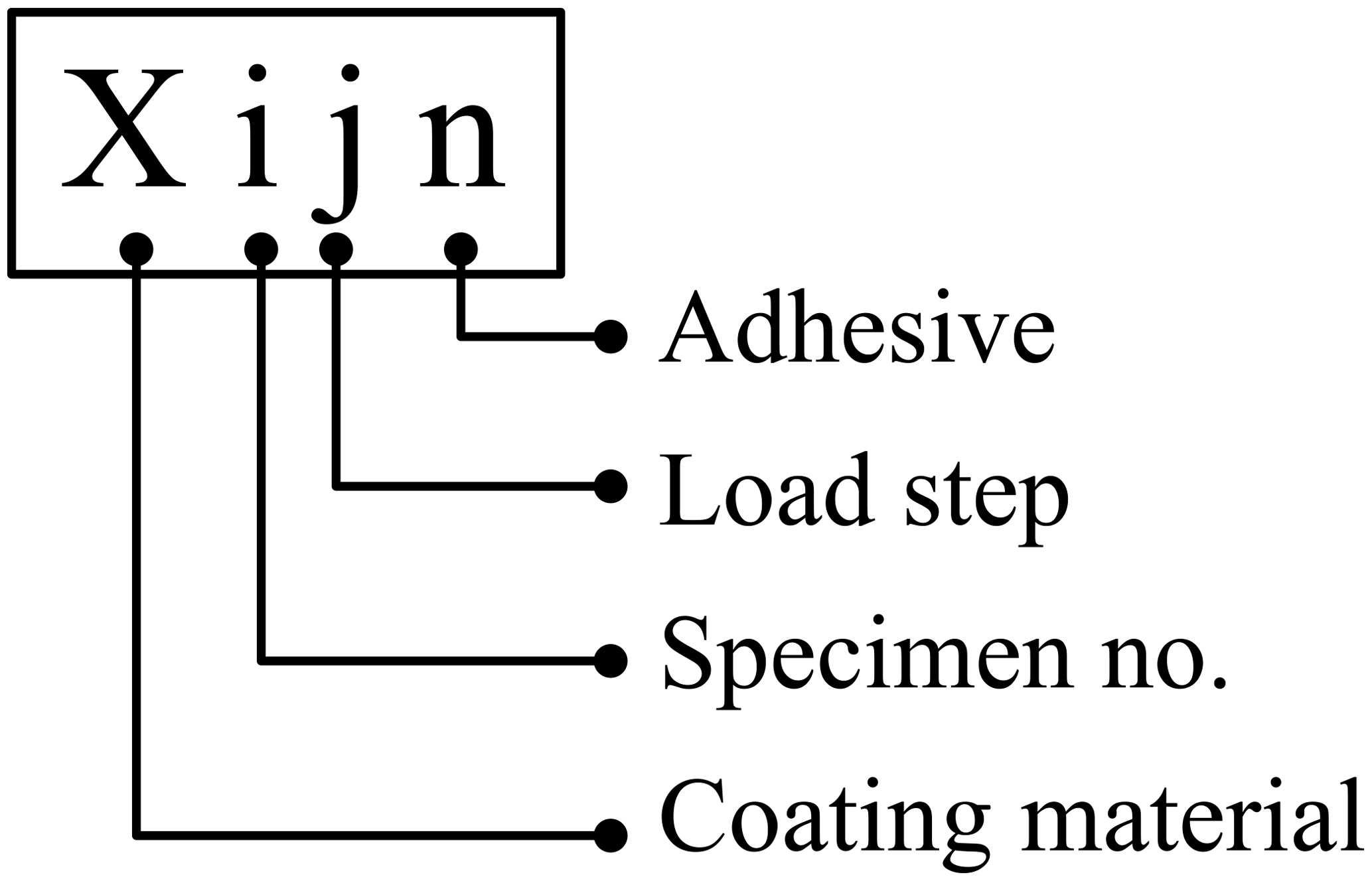
To reduce the amount of data, the comparison range of the respective adhesive was removed (59 fiber segments, 15 cm), and measurement errors were filtered using cubic spline interpolation. The resulting matrices for each specimen, load step, and adhesive were combined into a vector using the median in Eq. (1), represented as follows (Fig. 9):
For better comparison with the reference measurements and analytical calculation, the next step was to determine the arithmetic mean of the vector in Eq. (2):
The purpose of these experiments was to evaluate the distributed optical fiber sensor's strain measurement for usage in SHM, especially in embedded reinforcement bars used in concrete construction. For this purpose, 12 test specimens containing three different fiber coatings and six different adhesives were examined.
Figure 10 depicts the mean strain value comparison of the different coating materials and adhesives with the photogrammetric reference measurement as well as the theoretical calculation for the three load steps. The results illustrate a high correlation between the reference measurement, the theoretical calculation, and the polyimide and Ormocer® coatings. Similarly, almost no variation exists between the polyimide coating and the Ormocer® coating, while high expansion losses occurred with the acrylate coating. Since the difference between the adhesives is negligible, the distinction in the strain (approx. 15 % for all load steps) among the acrylate fiber and the two other fiber types is based exclusively on the coating material and not on the adhesive.
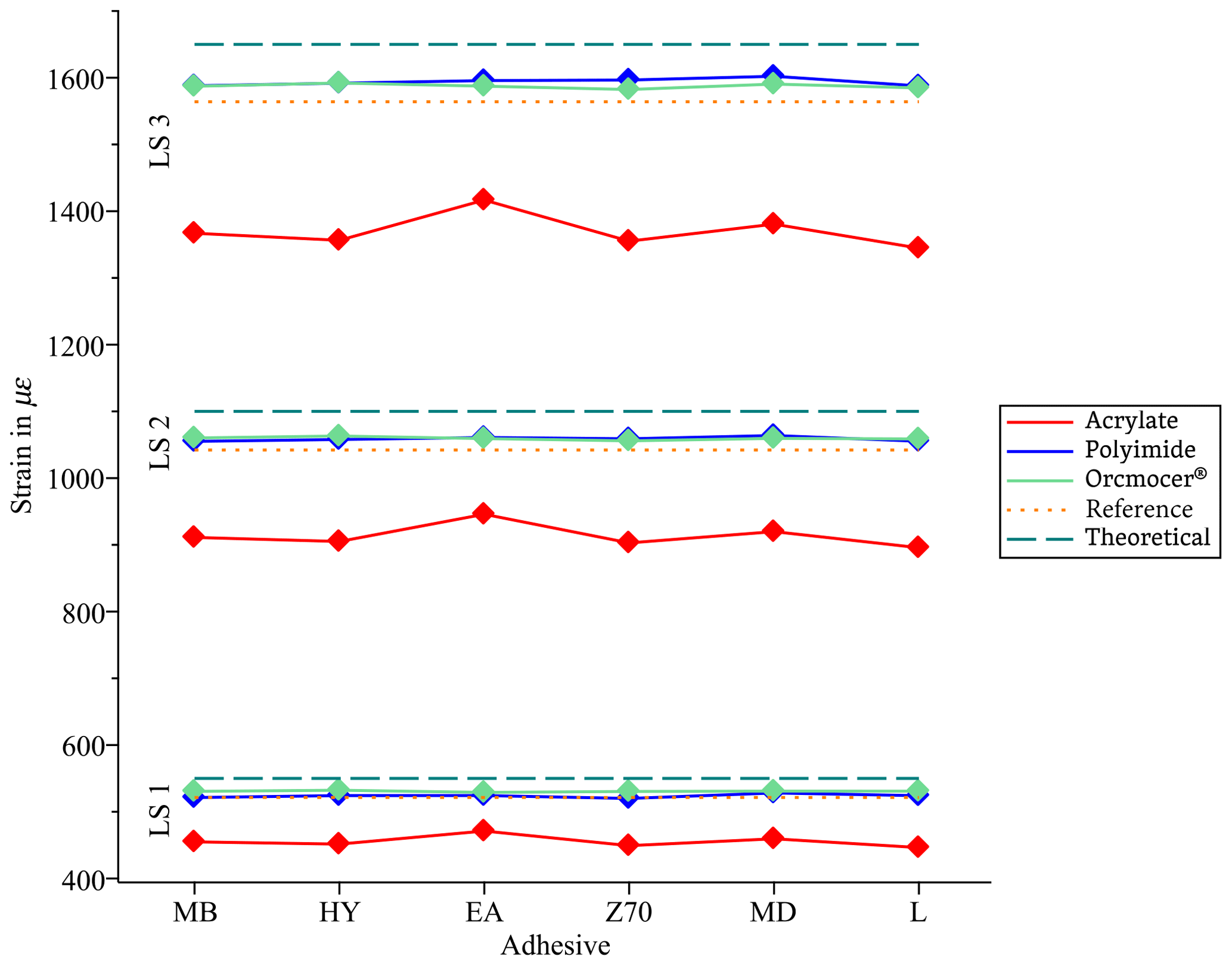
Figure 10Mean strain value comparison of different coating materials and adhesives with the reference measurement and the theoretical calculation for the three load steps.
The interpolated raw signal was used for a detailed comparison between the three fiber types. Figure 11 illustrates a comparison of the samples A131, P131, and O131 (load step three, M-Bond 200). While the strain curves of the polyimide and Ormocer® coatings are similar to the strain curve in Fig. 5, the acrylate coating is shifted because of slippage between the coating and the cladding of the fiber (cf. Fig. 1).
In summary, it can be shown that this test setup and arrangement is suitable for testing different adhesives with various coating materials up to the yield strength of steel. All specimens were prepared in the same way and displayed no artifacts. It was also shown that an acrylate coating is rather unsuitable for precise distributed optical strain measurement on steel surfaces.
Optical fiber strain measurement offers some interesting advantages over established measurement technologies that measure strain only at one specific point. However, the influence of slippage between the adhesive joint and the coating, as well as between the coating and cladding, should be investigated before usage in large-scale experiments and SHM. The preparation and execution of the adhesive joint used for these situations must be analyzed as well. The correct surface attachment of the fiber ensures the accurate reflection of the test specimen's strain values. In addition to the polyimide coating, the Ormocer® coating can also be used without restriction for strain measurements on steel surfaces.
The results demonstrate that all adhesives used in combination with the preparation described above can be applied to steel surfaces. The same applies to the Ormocer® and polyimide coatings, which exhibited almost the same strain values compared to that observed in the reference measurement. There are two reasons why the photogrammetric reference measurement produces lower strain values than the DOFS. First, photogrammetry has a higher measurement dispersion than DOFS. Second, photogrammetry only measures the change in the position of the measuring marks (Fig. 6). The deflection between the measurement marks, as a form of an arc length, is missing. Unlike the two other coating materials, the acrylate coating cannot reflect the real strain curve. Since the loss of strain across the adhesive layer between the adhesives appears almost identical, it is assumed that the loss of strain observed in the acrylate coating was caused by slippage between the coating and cladding. Compared to the analytical calculation, both measurement methods have lower strain values. It is assumed here that there is a deviation between the forces indicated by the testing machine and the forces imparted on the test specimens. There may also be minor deviations from the actual test setup and design (cf. Fig. 4) that contribute to this misalignment.
The study provides a foundation for exploiting the advantages of DOFS, especially in SHM and reinforced concrete construction. However, further research is still required for use on steel reinforcements in concrete. For instance, the adhesive joint and various coating materials must be observed under the influence of moisture and in an alkaline environment. Here, it must be clarified what influence these effects have on the displayed strains. In this context, the long-term stability must be investigated as well. Both sensor cables and covers can be used for mechanical protection against potential concerns, such as internal vibrators and aggregates. In this context, the influence that a cover or sensor cable has on the transmitted strains must be evaluated. Another important aspect, which has not been extensively studied, is loading conditions above the yield strength of steel. Preliminary investigations by the author have indicated that some types of adhesives are not suitable for such loads. It is unclear what influence the coating has on the strain transfer under such loading conditions.
This study compared optical fibers with three different coatings that were affixed to precision flat steel specimens using six different adhesives. If adhesive joints are prepared and executed as mentioned above, accurate and reproducible results can be achieved using DOFS based on Rayleigh scattering up to the yield strength of the steel. The following conclusions were drawn from the discussion above:
-
The preparation of the bonding area and the design of the adhesive joint are essential for the accurate transmission of the strain from the material to the fiber.
-
Ormocer® and polyimide coatings correlate closely with the reference measurement and the analytical calculation up to the yield strength of the steel specimen.
-
In the case of the acrylate fiber, a high loss of strain occurred due to slippage between the coating and cladding, which shifted the strain curve produced by the four-point bending test.
-
All six adhesives used in this study had similar results and can, therefore, be implemented without restriction for similar applications.
-
The high data volume requires an effective evaluation process to clearly interpret the results.
The datasets used and analyzed during the current study are available from the corresponding author on reasonable request.
MW carried out the experiments with the distributed fiber optic sensors, evaluated the data in relation to the topic, and wrote the final paper. KH accompanied the experiments and advised on the conceptual design of the paper. All authors read and approved the final paper.
The authors declare that they have no conflict of interest.
This article is part of the special issue “Sensors and Measurement Systems 2018”. It is a result of the “Sensoren und Messsysteme 2018, 19. ITG-/GMA-Fachtagung”, Nuremberg, Germany, from 26 June 2018 to 27 June 2018.
This research is co-financed by tax revenues on the basis of the budget
adopted by the members of the Saxon Parliament (promotion reference:
K-7531.20/434-14; SAB no. 100316843). Furthermore, Springer Nature Author
Services proofread the paper.
Edited by:
Jürgen Czarske
Reviewed by: two anonymous referees
Baqersad, J., Poozesh, P., Niezrecki, C., and Avitabile, P.: Photogrammetry and optical methods in structural dynamics – A review, Mechanical Systems and Signal Processing, Mech. Syst. Signal Pr., 86, 17–34, https://doi.org/10.1016/j.ymssp.2016.02.011, 2017.
Barrias, A., Rodriguez, G., Casas, J. R., and Villalba, S.: Application of distributed optical fiber sensors for the health monitoring of two real structures in Barcelona, Structure and Infrastructure Engineering, Struct. Infrastruct. E., 14, 967–985, https://doi.org/10.1080/15732479.2018.1438479, 2018.
Brockmann, W.: Interface reactions and their influence on the long term properties of metal bonds, in: Bicentennial of Materials Progress/SAMPE, Azusa, USA, 6–8 April 1976, 383–397, 1976
Brockmann, W., Geiß, P. L., Klingen, J., and Schröder, K. B.: Adhesive Bonding: Materials, Applications and Technology, Wiley-VCH, Weinheim, Germany, 2009.
Cheng, C.-C., Lo, Y.-L., Pun, B. S., Chang, Y. M., and Li, W. Y.: An investigation of bonding-layer characteristics of substrate-bonded fiber Bragg grating, J. Lightwave Technol., 23, 3907–3915, 2005.
Czarske, J. and Müller, H.: Heterodyne detection technique using stimulated Brillouin scattering and a multimode laser, Opt. Lett., 19, 1589, https://doi.org/10.1364/ol.19.001589, 1994.
Davis, M., Hoult, N. A., and Scott, A.: Distributed strain sensing to determine the impact of corrosion on bond performance in reinforced concrete, Constr. Build. Mater., 114, 481–491, https://doi.org/10.1016/j.conbuildmat.2016.03.205, 2016.
DIN Deutsches Institut für Normung e.V.: Hot rolled products of structural steels – Part 2: Technical delivery conditions for non-alloy structural steels, 77.140.45, 2004.
DTG coating Ormocer®-T for Temperature Sensing Applications: available at: http://www.fbgs.com/website/fbgs/assets/files/technical-info/Introducing_and_evaluating_Ormocer-T_for_temperature_sensing_applications.pdf, last access: 18 September 2018.
Ebnesajjad, S.: Handbook of Adhesives and Surface Preparation: Technology, Applications and Manufacturing (Plastics Design Library), William Andrew, Oxford, UK, 2010.
Ebnesajjad, S. and Landrock, A. H.: Adhesives Technology Handbook (Plastics Design Library), William Andrew, London, UK, 2014.
Froggatt, M. and Moore, J.: High-spatial-resolution distributed strain measurement in optical fiber with Rayleigh scatter, Appl. Opt., 37, 1735–1740, 1998.
Gifford, D. K., Soller, B. J., Wolfe, M. S., and Froggatt, M. E.: Distributed fiber-optic temperature sensing using Rayleigh backscatter, in: 2005 31st European Conference on Optical Communication/ECOC 2005, Glasgow, UK, 25–29 September 2005, 511–512, 2005.
Horiguchi, T., Shimizu, K., Kurashima, T., Tateda, M., and Koyamada, Y.: Development of a distributed sensing technique using Brillouin scattering, J. Lightwave Technol., 13, 1296–1302, https://doi.org/10.1109/50.400684, 1995.
Hoult, N. A., Ekim, O., and Regier, R.: Damage/deterioration detection for steel structures using distributed fiber optic strain sensors, J. Eng. Mech., 140, 04014097, https://doi.org/10.1061/(ASCE)EM.1943-7889.0000812, 2014.
Inaudi, D. and Glisic, B.: Application of distributed fiber optic sensory for SHM, Proceedings of the ISHMII-2, 1, 163–169, 2005.
Leung, C. K. Y., Wan, K. T., Inaudi, D., Bao, X., Habel, W., Zhou, Z., Ou, J., Ghandehari, M., Wu, H. C., and Imai, M.: Review: Optical fiber sensors for civil engineering applications, Materials and Structures, Mater. Struct., 48, 871–906, https://doi.org/10.1617/s11527-013-0201-7, 2015.
Lopez-Higuera, J. M., Rodriguez Cobo, L., Quintela Incera, A., and Cobo, A.: Fiber Optic Sensors in Structural Health Monitoring, J. Lightwave Technol., 29, 587–608, https://doi.org/10.1109/JLT.2011.2106479, 2011.
New Highly Flexible Cyanoacrylates: LOCTITE® 4902™ and LOCTITE® 4903™, https://www.ellsworth.com/globalassets/literature-library/manufacturer/henkel-loctite/henkel-loctite-white-paper_flexible-cyanoacrylates-loctite-4902-and-4903.pdf, last access: 19 November 2018.
ODiSI Fiber Optic Sensor Installation Guide: available at: https://lunainc.com/wp-content/uploads/2017/01/TN_Applying-Strain-Sensors_RevB_v1.pdf, last access: 18 September 2018.
Parker, T. R., Farhadiroushan, M., Handerek, V. A., and Roger, A. J.: A fully distributed simultaneous strain and temperature sensor using spontaneous Brillouin backscatter, IEEE Photonic. Tech. L., 9, 979–981, https://doi.org/10.1109/68.593372, 1997.
Quiertant, M., Baby, F., Khadour, A., Marchand, P., Rivillon, P., Billo, J., Lapeyrere, R., Toutlemonde, F., Simon, A., Cordier, J., and Renaud, J. C.: Deformation Monitoring of Reinforcement Bars with a Distributed Fiber Optic Sensor for the SHM of Reinforced Concrete Structures, in: NDE, Seattle, United States, 10 pp., 2012.
Samiec, D.: Distributed fibre-optic temperature and strain measurement with extremely high spatial resolution, Photonic International, Photon. Int., 6, 10–13, 2012.
Schilder, C., Schukar, M., Steffen, M., and Krebber, K.: Structural health monitoring of composite structures by distributed fibre optic sensors, in: Proceedings of the 5th International Symposium on NDT in Aerospace, Singapore, Republic of Singapore, 13–15 November 2013, 12, 2013.
Schlüter, V. G.: Entwicklung eines experimentell gestützten Bewertungsverfahrens zur Optimierung und Charakterisierung der Dehnungsübertragung oberflächenapplizierter Faser-Bragg-Gitter-Sensoren, Ph D. thesis, Bundesanstalt für Materialforschung und -prüfung (BAM), Berlin, 69 pp., 2010.
Skontorp, A., Levin, K., and Benmoussa, M.: Surface-mounted optical strain sensors for structural health monitoring of composite structures, in: Proceedings of the 16th Annual Technical Conference of the American Society for Composites, Blacksburg, VA, USA, 10–12 September 2001, 970–982, 2001.
Song, K. Y., Chin, S., Primerov, N., and Thévenaz, L.: Time-domain distributed fiber sensor with 1 cm spatial resolution based on Brillouin dynamic grating, J. Lightwave Technol., 28, 2062–2067, 2010.
Technical data sheet MD MEGABOND 2000: available at: http://www.marstondomsel.de/images/downloads/TDB_DE_GB/GB_TDB_MD_MMB2000_Megabond.pdf, last access: 18 September 2018.
Weisbrich, M., Holschemacher, K., and Kaeseberg, S.: Comparison between different Fiber Optical Strain Measurement Systems Based on the Example of Reinforcing Bars, Procedia Engineer., 172, 1235–1242, https://doi.org/10.1016/j.proeng.2017.02.145, 2017.
Zhou, L., Wang, F., Wang, X., Pan, Y., Sun, Z., Hua, J., and Zhang, X.: Distributed Strain and Vibration Sensing System Based on Phase-Sensitive OTDR, IEEE Photonic. Tech. L., 27, 1884–1887, https://doi.org/10.1109/lpt.2015.2444419, 2015.