the Creative Commons Attribution 4.0 License.
the Creative Commons Attribution 4.0 License.
 | 06 Mar 2018
IO-Link Wireless enhanced factory automation communication for Industry 4.0 applications
Ralf Heynicke
Dmytro Krush
Christoph Cammin
Gerd Scholl
Bernd Kaercher
Jochen Ritter
Pascal Gaggero
Markus Rentschler
In the context of the Industry 4.0 initiative, Cyber-Physical Production Systems (CPPS) or Cyber Manufacturing Systems (CMS) can be characterized as advanced networked mechatronic production systems gaining their added value by interaction with the ambient Industrial Internet of Things (IIoT). In this context appropriate communication technologies and standards play a vital role to realize the manifold potential improvements in the production process. One of these standards is IO-Link. In 2016 more than 5 million IO-Link nodes have been produced and delivered, still gaining increasing acceptance for the communication between sensors, actuators and the control level. The steadily increasing demand for more flexibility in automation solutions can be fulfilled using wireless technologies. With the wireless extension for the IO-Link standard, which will be presented in this article, maximum cycle times of 5 ms can be achieved with a probability that this limit will be exceeded to be at maximum one part per billion. Also roaming capabilities, wireless coexistence mechanisms and the possibility to include battery-powered or energy-harvesting sensors with very limited energy resources in the realtime network were defined. For system planning, setup, operation and maintenance, the standard engineering tools of IO-Link can be employed so that the backward compatibility with wired IO-Link solutions can be guaranteed. Interoperability between manufacturers is a key requirement for any communication standard, thus a procedure for IO-Link Wireless testing is also suggested.


During the last years WirelessHART (HART-FieldComm Group, 2018; IEC 62591, 2016) has become the de facto standard in process automation, relying on the physical layer of the IEEE standard 802.15.4 (IEEE 802.15.4, 2015) and specifying additional transport and application layers. As the requirements with respect to start-up and latency times, device density, physical dimensions, and installation costs are more demanding in factory automation applications (VDI/VDE 2185, 2007), a comparable standard has not been established in this environment up to now. The investigations and developments described in this article are focused on the wireless extension (IO-Link Community, 2017) of the IO-Link standard (IEC 61131-9, 2013; IO-Link Community, 2013), which has been initiated by the Profibus User Organisation (PNO) and the IO-Link community several years ago. Since the IO-Link standard is already well established in the field for sensor/actuator communication (Balluff GmbH, 2013; IO-Link Community, 2010, 2016), the discussion of the IO-Link standard in the next section is limited to the necessary information to understand the characteristics and properties of the wireless extension, given in IO-Link Community (2017). The classic multi-level communication model of an automation system is shown in Fig. 1, where the target applications for IO-Link communication are on the sensor/actuator level of the automation pyramid.
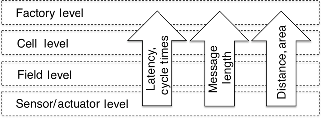
Figure 1Classic multi-level organization of an industrial communication system for automation applications.
According to (Frotzscher et al., 2014), wireless communication requirements in industrial environments can roughly be categorized by the following parameters: system availability, redundancy requirements, safety and security level, electromagnetic compatibility with classical industrial interferers such as induction heaters and switch-mode power supplies, coexistence behaviour with already installed wireless systems, type of data traffic, latency times, message lengths and spectrum allocation requirements, number of communicating stations, coverage area, mobility support, handover mechanisms, and integration availability. All these requirements are addressed by the proposed IO-Link Wireless specification. Performance characteristics for wireless sensor/actuator communication systems are usually defined with response times in the order of 10 ms or even lower and with up to 100 sensors and actuators within a production cell extending a few metres (Frotzscher et al., 2014; Koerber et al., 2007; Krush et al., 2016). For application areas requiring coexistence with already installed wireless systems, e.g. Wi-Fi, radio channel blacklisting has been implemented. Together with the protocol-inherent mechanisms of IO-Link Wireless for time and frequency diversity, this provides a reliable and robust wireless technology for real-time communication of the sensors and actuators to the overlaying production process (Fig. 2).
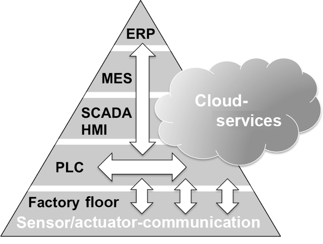
Figure 2New standards and technologies enable horizontal and vertical communication systems integration and to break-up the classical automation pyramid, according to Jeschke et al. (2017); VDI/VDE (2013).
With the introduction of CMS and IIoT in factory automation, this highly structured communication architecture will gradually be modified and improved with highly decentralized networked services (Jeschke et al., 2017; VDI/VDE, 2013). In this context IO-Link and IO-Link Wireless are seen as enabling technologies for such services, offering full networking capability vertically down to the sensors and actuators on the shop floor and up to the enterprise resource planning (ERP) tool via the SCADA (supervisory control and data acquisition) / HMI (Human–machine interface) level and the MES (manufacturing execution systems) layer and horizontally across the various fieldbus platforms (PLC, programmable logic controller) on the basis of an already internationally established communication standard (Fig. 2).
OPC UA (Open Platform Communications Unified Architecture; OPC Foundation, 2017a, c) is discussed as the “one fits all” standard for future automation systems and offers promising features, such as the ability to remotely discover and configure devices in an automation network without the need for prior knowledge of the network topology or the identities of its components (Rentschler et al., 2016). Activities to integrate IO-Link within OPC UA have thus recently been started within the IO-Link community to create a companion specification OPC UA for IO-Link (OPC Foundation, 2017b). Since on the higher levels, IO-Link Wireless is fully compatible with wired IO-Link, IO-Link Wireless is implicitly fully covered.
As indicated in Fig. 3 the open interface standard IO-Link, as described in IEC 61131-9 (2013), offers a fieldbus-neutral communication between the sensor/actuator level and the control level. It specifies a serial, half-duplex point-to-point connection for digital communication and energy supply. An IO-Link system typically consists of an IO-Link fieldbus gateway, the IO-Link master, providing one or more master ports, each of which is connected to a single IO-Link device. Devices can be sensors, actuators, RFID readers, valves, motor starters or simple I/O modules. Additionally, the standard IO-Link system comprises engineering tools for sensor/actuator configuration and parameter assignment. The following basic data types are defined:
-
Process data with a length of up to 32 bytes, which are exchanged with every communication cycle.
-
Value status data indicating if the process data are valid or not, which are also exchanged cyclically.
-
Parameter and diagnostic data such as identification information, settings, warnings and errors, which are exchanged on request.

Figure 3Example of a wireless enhanced system architecture based on IO-Link according to (IO-Link Community, 2016).
To give an example: at a maximum speed of 230 kBaud it takes 400 µs to exchange 2 bytes of process data and 1 byte of on request data between the IO-Link master and the device (IO-Link Community, 2016). Input Output Device Description (IODD) files are defined and available for each IO-Link device to facilitate vendor-independent system integration. These files contain communication properties such as the supported baud rate, device ID, manufacturer ID, device specific data and parameters as well as a description of the process data provided by the sensor or actuator. For system configuration, engineering tools are available that make use of the IODD files, allowing high-level configurability of the IO-Link devices via the IO-Link master. The main tasks are the assignment of the devices to the master ports and address/parameter assignment (IO-Link Community, 2010).
How the IO-Link Wireless system will be embedded in the industrial communication architecture is illustrated in Fig. 4. From a user's perspective there is no difference in the operation of the devices, i.e. sensors and actuators, whether they are connected to the master by wire or wirelessly. Also standard engineering tools for sensor/actuator configuration and parameter assignment can be employed. These can be extended to optimize radio link quality and coexistence behaviour. The necessary parameters for wireless communication were added to the standard IODD files. Additionally, conventional IO-Link devices can also be coupled wirelessly to the IO-Link master utilizing a Wireless IO-Link Bridge module.

IO-Link Wireless incorporates mechanisms for Discovery and Pairing to detect and authenticate devices before operating them in the application context. The Discovery procedure enables a master to discover unpaired devices in its range. This is achieved by regularly issuing Scan Request messages. Any unpaired device that receives such a Scan Request, answers with a Scan Response message that contains the unique address (Unique ID) of the device. An actual connection between master and device can then be established via the Pairing procedure. If the Unique ID received in the Discovery procedure is listed in the master's pre-engineered configuration of allowed devices, the master autonomously pairs the device by issuing a Pairing Request message that gets responded by a Pairing Response message from the device. In this context the hopping sequence table is also transferred to the device. When this procedure is successfully completed, the master notifies its application (PLC) that the device is present and ready to be operated by the application for cyclic process data exchange.
These standard mechanisms of Discovery and Pairing can also be utilized for Roaming in the context of control system applications (Rentschler, 2017). This is simply achieved within the system by notifying the PLC about the connection states of the roaming devices and designing the PLC program accordingly. When a roaming device appears in the coverage area of a master, the PLC gets notified and can decide to exchange process data with the device. In case the link quality drops below a certain threshold value, because a device is moving away from its master, an autonomous Unpairing procedure will be initiated and the control program will execute the next process step or wait in its current execution state for the next allowed roaming device to appear. This coordination of handover decisions with control flow information eliminates the need for complex technical solutions within the IO-Link Wireless protocol stack. The relevant performance indicator for the handover mechanism is the duration of the Handover Connect phase, thus the time between the roaming device becoming visible for the new master and actual start of process data communication. This can be guaranteed in the worst case to be below 1 s.
It has been found that the physical layer of Bluetooth Low-Energy devices optimally fits to the requirements for an efficient wireless data exchange. To comply with regulatory standards (ETSI, 2015, 2016) the maximum RF transmission power is smaller than 10 mW. The 2.45 GHz ISM-band (industrial, scientific, medical band) has been chosen due to multiple reasons: global availability, the availability of low-power RF transceivers and the capability to support the communication load of several dozens of wirelessly connected sensors and actuators due to an allocated bandwidth of 80 MHz. To guarantee a highly reliable and well-defined temporal behaviour of cyclic data transfer in the presence of channel fading effects, a combination of a frequency- and time-division media access scheme (F/TDMA) has been employed. Downlink (DL) massages from the IO-Link master to the devices and uplink (UL) messages from the devices to the master are exchanged in a half-duplex mode in a defined time frame, as is shown in Fig. 5. Initially, a cycle time of 10 ms was specified (Krush et al., 2016), but this could later be optimized to 5 ms. In Fig. 5 one RF cycle with a duration of 5 ms is shown, allowing two retransmits of cyclic data within three sub-cycles, each having a duration of approximately 1.66 ms. With a length of 416 µs for the downlink telegram and a length of 200 µs for an uplink telegram, four time slots for uplink communication can be provided. The organization interval (Fig. 5) is the time which is needed for frequency change and/or RX/TX switching of the RF transceivers. For the realization of the IO-Link Wireless master, a modular architecture has been defined (Koerber et al., 2007, 2008) that allows masters equipped with up to five radio transceivers to be realized, each serving several wireless IO-Link devices on the same frequency of operation, i.e. the same frequency track. A single-track master with one RF transceiver can handle up to eight wireless devices. Multi-track masters with five transceivers can thus accommodate 40 wirelessly connected sensors and actuators.
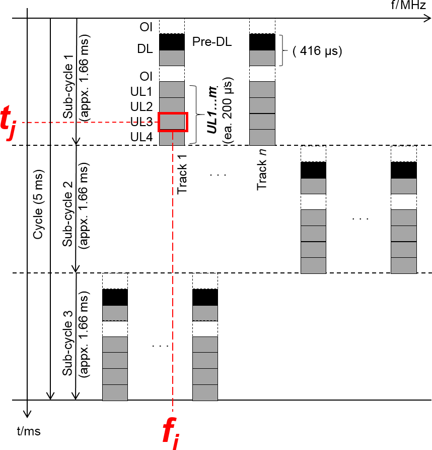
Figure 5IO-Link Wireless medium access. OI = Organization Interval, DL = Downlink, UL = Uplink.
Suitable frequency hopping algorithms have been developed to mitigate channel fading, to improve coexistence behaviour and to allow roaming of devices between masters (Krueger et al., 2012; Krush et al., 2016). Generally, the time-variant and frequency selective behaviour of a radio channel can roughly be described by two parameters, which are coherence time and coherence bandwidth (Koerber et al., 2007; Rappaport, 2001; Shankar, 2012). These parameters describe an average temporal period and average frequency spacing, respectively, within which the radio channel does not change its characteristics (Rappaport, 2001; Shankar, 2012). According to the definition in Koerber et al. (2007), in an industrial environment the coherence time typically lies between 2 and 15 ms and the respective coherence bandwidth between 6 and 60 MHz (Koerber et al., 2007; Rappaport, 2001). The frequency spacing between two frequency hops is adjusted in a way that the typical coherence bandwidth of an industrial radio channel is exceeded.
Several concepts have been defined to reduce energy consumption to also allow devices with very limited energy resources to be integrated into the wireless communication system, such as long-term operable battery-powered devices. One example for energy optimization concepts is that the downlink sequence, DL, has been subdivided into a pre-downlink telegram (Pre-DL) and an extended part, as is indicated in Fig. 5. This will significantly reduce the RF receiver uptime and thus the energy consumption. The idea behind it is as follows: if, for example, an energy-autonomous sensor has just sent an RF telegram, this sensor expects only a short acknowledgement (ACK) signal from the master in the next downlink protocol. All of the ACK signals for energy-limited sensors are positioned in the Pre-DL so that they only have to listen for the master response over a very short time interval and can than go back into sleep mode immediately.
The RF system architecture and the system parameters have been adjusted such that a maximum packet error rate of 10−3 per sub-cycle can be achieved. Thus, with two possible retransmits, the probability that the maximum latency time of 5 ms for cyclic data transfer is exceed is as low as 10−9. This value is comparable with wired communication solutions. Assuming a packet error rate below 0.1 %, the acyclic data transfer can be interwoven with the transfer of cyclic data. This is depicted in Fig. 6, showing the normal mode of operation. Within one RF cycle master and device only require one single sub-cycle for data exchange and ACK. Thus, the other two sub-cycles can be used for the transmission of acyclic data.
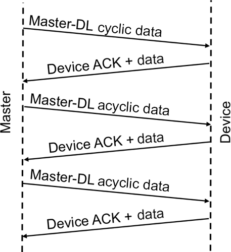
The worst case is shown in Fig. 7a, where the ACK signal from the device is missed by the master. In this case the master starts a retry, which is also not acknowledged by the sensor generating a second retry. Acyclic data exchange is not real-time critical. If there would be an error during acyclic data transfer, as is shown in Fig. 7b, data transmission will be repeated until the information will be acknowledged.

Figure 7Data transfer errors. (a) Worst-case scenario: double error occurring in cyclic data exchange. (b) Error occurring in acyclic data exchange.
For an improved coexistence behaviour, two mechanisms were implemented, frequency hopping and blacklisting, which allows for operating the wireless sensor/actuator network with low packet-error rates even in industrial plants where three Wi-Fi bands are allocated in the 2.45 GHz band, as is shown in Fig. 8. It was also investigated how the Wi-Fi systems are affected by the IO-Link Wireless system and another wireless system, using the same physical layer (Cammin et al., 2016). With the help of a wired measurement setup no significant decrease in the performance of the Wi-Fi system could be detected in the presence of that system which is conformable to the IO-Link Wireless system.

Figure 8Spectrogram of the RF traffic in the 2.45 GHz band. The IO-Link Wireless network comprises one master and two devices. RF communication is carried out between the occupied Wi-Fi bands. The downlink (DL) signal is followed by the uplink (UL) signals. In the spectrogram they can be distinguished by their different signal powers.
A test method for narrowband wireless sensor/actuator networks is presented in Cammin et al. (2017a), facilitating affordable and efficient performance and compliance tests prior to the deployment of the wireless communication systems. As will be demonstrated in the following subsections, this test method can also be utilized for IO-Link Wireless tests as well.
In order to ensure the reliability of IO-Link Wireless in the field, as proposed in Sect. 4, pretests in well-defined, representative and reproducible environments can be accomplished. Generally, the performance degradation of a wireless system can have multiple reasons, e.g. (self)-interference, time jitter, frequency drift, frequency offset, modulation impairments or an insufficient system dynamic range. These imperfections influence the frame- and bit-error probabilities (FEP, BEP), which are integral indicators for the system performance. In order to ensure that even in a worst-case scenario (e.g. multipath environment with fading radio channels and a large number of IO-Link Wireless devices) a high performance will always be ensured, the system can be tested under full communication load. These tests have to be also carried out for equipment under test (EUT) with non-detachable integrated antennas, i.e. a sealed sensor. For these EUT, the test signals have to be coupled into the EUT via electromagnetic radiation.
6.1 Radio channel
If the coherence bandwidth is significantly larger than the transmission bandwidth of the wireless communication system, the radio channel can be considered as frequency-flat and is denoted as a narrowband channel, generally. The radio channel is commonly described by the complex transfer function H(f,t) of time t and frequency f (Rappaport, 2001). Phase or group delay variations in the radio channel can be neglected in the narrowband case (Rappaport, 2001).
The on-air packet lengths of 200 or 416 µs are well below the coherence time of the radio channel. The IO-Link Wireless system can be classified as narrowband communication systems (Heynicke et al., 2017; Krush et al., 2016). According to Fig. 5, the IO-Link Wireless MAC is arranged in n frequency tracks and m time slots and thus the behaviour of the radio channel can be simplified to for a particular frequency channel i and a particular time slot j. As a result, one single time-variant attenuation factor associated with each narrowband frequency track is sufficient to emulate all radio channels appropriately.
Various models have been derived for the small-scale fading behaviour of indoor radio channels (Rappaport, 2001; Shankar, 2012) and it has been shown that the Rayleigh channel model can be considered as worst-case scenario, generally. Thus it is beneficial to qualify the wireless system according to it's behaviour for a radio channel with Rayleigh fading characteristics.
6.2 Test system setup
The measurement concept can be adopted from the wired IO-Link approach (IO-Link Community, 2014), where a device is tested against a Golden Master and a master is tested against a Golden Device. For the wireless system, the radio channel has also to be taken into account. Furthermore, the influence of interferers and other wireless systems on the IO-Link Wireless performance should be tested. The radio channel including optional interferes is denoted as Golden Channel in Fig. 9.
The EUT, either a device or a master, is logically linked via the Golden Channel to the Golden Master or Golden Device, respectively. This link can be realized by, e.g. coaxial cables for EUT with accessible antenna connectors. For EUT with integrated antenna, this link has to be realized via wireless radio wave propagation as in Sect. 6.5.

The test setup is based on Test Equipment (TE), which comprises at least a communication partner for the EUT, a radio Channel Emulator (CE), equipment to generate the signals of other system subscribers and components for RF signal distribution, e.g. coaxial cables (depicted as black connection lines in Fig. 9).
The CE emulates fading by applying the specific . To implement the CE, synchronized fast-switching attenuators can be used. The synchronously switching of the attenuators to the IO-Link Wireless protocol of the radio units allows for reducing the number of attenuators to one attenuator per frequency track.
When testing a system under full communication load, it is usually not practical to deploy the maximum allowed number of devices in a test setup. Instead, the signals of the devices are emulated by the test companion (TC): Similar to an ordinary device, the TC receives the DL signal from the master and configures itself. Thus, the TC emulates other devices by generating their UL and DL signals. Utilizing protocol synchronization, the same number of narrowband transmitters in the TC as frequency tracks (n in Fig. 5) is sufficient to emulate the full traffic of the communication system. In contrast to alternative implementations based on a vector signal generator or high-speed digital signal processing communication testers, this approach allows the use of the same narrowband transceivers as in standard IO-Link Wireless devices or master. This enables a very cost-efficient implementation of the TC.
Combining the ideas for the CE, TC and protocol-synchronization, all devices can accurately be emulated by their specific UL signals and their associated fading radio channel, i.e. . Furthermore, the parallel use of narrowband transceivers has the advantage that they have independent signal chains. In conjunction with an attenuator, which typically has an operating bandwidth of several gigahertz, a faded narrowband signal can be easily generated.
6.3 IO-Link Wireless device testing
In order to ensure both performance according to the IO-Link Wireless standard and interoperability between devices and masters from different vendors, the devices should be tested. Besides measurements of the packet error probability or repetitions of various received power levels, the devices should be asynchronously triggered as a realistic scenario, while the final timing at the Golden Master is monitored. The IO-Link Wireless protocol prescribes a strict and close timing. Due to our experience, measurements have shown that the total RF signal of many transceiver chips lasts longer than the on-air transmission time of the payload and the overhead (Krueger, 2017). This is caused by an (unmodulated) RF carrier signal in front of or after the on-air data transmission (Krueger, 2017). As a consequence devices assigned to adjacent time slots may interfere. To detect this impairment by testing, all other network devices up to the system capacity limit can also be emulated by the TC, as shown in Fig. 10. The EUT is embedded into the signals from the (golden) master and the emulated additional devices. In this example the EUT is assigned to frequency track i and time slot j. With the CE, the appropriate radio channel behaviour is provided, as described in Sect. 6.1. By performing FEP or BEP measurements, the overall EUT performance can be quantified.
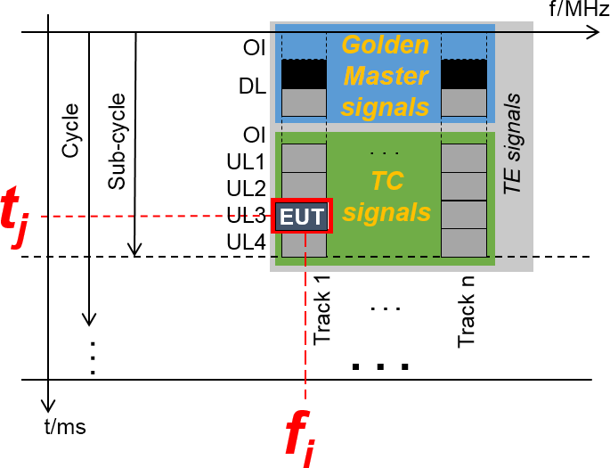
Figure 10A device as EUT: the signals from the TE (Test Equipment, light-gray) involve signals from the Golden Master (light-blue) and the TC (Test Companion, green), which are the emulated signals from additional devices.
6.4 IO-Link Wireless master testing
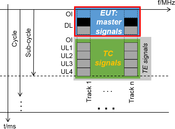
A master testing under full communication load is especially important, due to the high data transmission rate over time-critical interfaces and subsystems. As an example, the IO-Link Wireless protocol requires a fast RX to RX transition feasibility to capture successive uplink signals from different devices. At least parts of the data handling in a master is realized by serial processing, e.g. the communication over a wired network or fieldbus, and thus possible bottlenecks should be identified. Furthermore, the same general approach as for device testing applies for master testing too. In this setup the TC is the communication partner for the EUT (master) emulating the UL signals of all devices, as shown in Fig. 11.
6.5 Equipment under test (EUT) with integrated antenna
To couple signals wirelessly into an EUT with integrated antennas, shielded test enclosures (e.g. semi/full anechoic chamber, GTEM-cell (gigahertz transverse electromagnetic cell), reverberation chamber) were suggested (Schwab and Kürner, 2011). A reverberation chamber (RC) consists of a shielded volume, which is equipped with mode stirrers. Usually these are rotating or moving plates to stir the electromagnetic fields within the chamber step-wise or continuously (Holloway et al., 2006; Schwab and Kürner, 2011). Besides these mechanical mode stirrers, other types of mode stirrers can also be utilized (Rosengren et al., 2001).
In contrast to most other test enclosures, RCs provide stochastically isotropic fields (Schwab and Kürner, 2011) and intrinsic radio channels with Rayleigh (or Rician) fading behaviour (Corona et al., 2000; Holloway et al., 2006; Kildal et al., 2012; Kostas and Boverie, 1991). This means that for a full mode-stirring cycle the corresponding set of measurements results in an isotropic and homogeneous environment for the EUT.
Figure 12 shows a photo inside a RC with a device as EUT. The RC shown here is equipped with a turntable and two planar mode stirrers. For the electromagnetic field excitation, a fixed antenna with switchable polarization is mounted behind a shielding blade. The latter is installed in order to minimize a direct path between the fixed antenna and the EUT. The reference antenna shown here is used for calibration and validation purposes. A detailed description of this RC is also given in (Cammin et al., 2017b).
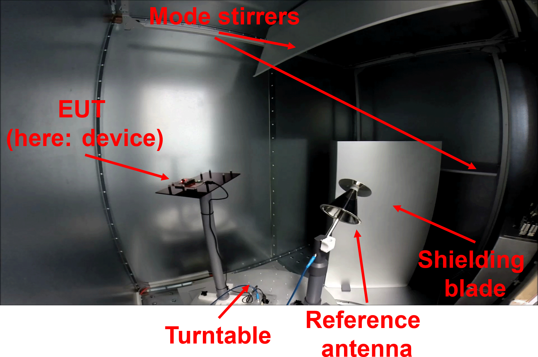
Figure 12Photo inside a RC. (in order to capture the whole interior of the RC, the photo was taken using a fisheye lens and is therefore distorted at the edges).
The coherence bandwidth of the Rayleigh channel in a RC can be adjusted to the values as measured in industrial environments (Chen et al., 2011; Coder et al., 2010), i.e. the intrinsic channel can be tuned to emulate a particular environment by loading the RC, e.g. with appropriate absorbers (Cammin et al., 2017b; Chen et al., 2011; Coder et al., 2010; Schwab and Kürner, 2011). This allows for omitting an additional CE if a Rayleigh channel is desired (Lötbäck et al., 2015).
For quality testing during the production process an even more simplified approach is suggested, which is similar to the relative measurements in (ETSI, 2015). First, a prototype of the series product is tested in a RC according to the approach presented above. In a second step the same prototype is mounted in a small absorber chamber, or more specifically in a test fixture (TF), instead of a RC and the test is repeated. The measured FEP/BEP obtained in the TF can then be used as reference values. In contrast to a test in a RC, a TF does not provide an (statistically) isotropic and homogeneous field distribution, but the measured reference values can be used if the EUT is always mounted in the same position and orientation within the TF.
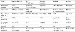
IEC 62948 (2017)IEEE 802.15.1 (2005)IEEE 802.15.1 (2005)IEEE 802.15.1 (2005)(Verhappen, 2016)Table 1Selection of requirements for different wireless standards addressing factory automation.
Due to rapidly changing technology approaches and innovative solutions for cross linking all types of business processes, current communication standards in the field of factory automation will continue to evolve and new standards will also evolve. As already indicated in the introduction (Sect. 1) different application domains for wireless industrial communication systems exist. The guideline VDI/VDE 2185 (2007) lists five different application fields: process automation, infrastructure plants, building automation, logistics/transport and factory automation. The target application domain for IO-Link Wireless is factory automation with the challenge that the requirements with respect to reliability, device density and reaction/cycle times are typically harder to achieve compared with the other application domains. In order to classify and assess the new communication standard IO-Link Wireless current important technology trends and standards are shortly outlined without claiming completeness of the following enumeration.
7.1 WISA and WSAN-FA
The acronym WISA stands for Wireless Interface for Sensors and Actuators and was originally developed as a proprietary standard by ABB (ABB, 2006; Vallestad, 2012). In the meanwhile many systems in the field have demonstrated that the system works well even under harsh factory environmental conditions. Therefore, WISA is still the reference system for newer communication systems and also for IO-Link Wireless. Some basic ideas of the WISA system can still be found within the IO-Link Wireless standard.
For bidirectional communication, frequency division duplex (FDD) is used. According to ABB (2006) one base station supports up to 120 wireless devices. Up to three base stations can be operated within one manufacturing cell “without significant loss of performance” (ABB, 2006) at the same time. The data sheet lists a 5 m range for an industrial environment and 15 m typical range (ABB, 2006). Latency time is stated to be typically 20 ms for 99.99 % of all cases and to be 34 ms maximum (ABB, 2006). Wi-Fi (IEEE 802.11 WLAN, 2012) channels can be blacklisted in segments in order to improve coexistence behaviour.
The principles of the proprietary communication solution have been introduced into the standard WSAN-FA, which stands for Wireless Sensor-Actuator Network - Factory Automation (Vallestad, 2012). Based on WSAN-FA, no product developments have been carried out, instead WSAN-FA has been enhanced and renamed to IO-Link Wireless IO-Link Community (2017). A detailed description of the transition is given in Krush et al. (2016). Currently, several companies are in the development phase to bring new products on the market during the next months.
7.2 Industrial Bluetooth
Phoenix Contact offers various solutions based on different Bluetooth (Bluetooth SIG, 2017) versions. The first version physical layer is based on IEEE 802.15.1 (2005), and thus frequency hopping spread spectrum (FHSS) in the 2.45 GHz band is utilized. Under the name Industrial Bluetooth, a communication system to bridge ethernet signals via Bluetooth is offered (Phoenix Contact, 2017a, d). The second generation combines radios for Wi-Fi, Bluetooth Version 2.1+EDR and Bluetooth Low Energy 4.0 (Phoenix Contact, 2017b). Up to seven devices can be connected (Phoenix Contact, 2017a). The so-called update time is stated to be greater than 16 ms (Phoenix Contact, 2017b). The Wireless-MUX system, based on Bluetooth 4.0, transmits 16 digital and two analog signals bidirectionally (Phoenix Contact, 2017d). In a point-to-point topology the number of network devices is limited to two (Phoenix Contact, 2017c). The transmission time is stated to be greater than 10 ms (Phoenix Contact, 2017c). A study on the coexistence performance of industrial-adopted Bluetooth is presented in Weczerek and Pape (2010). According to that survey, a strict blacklisting is implemented, but not operating during the initial startup. Up to now, a vendor-independent standard or profile for industry-adopted Bluetooth has not emerged.
7.3 WIA-FA
Wireless Networks for Industrial Automation – Factory Automation (WIA-FA) has recently became an international standard under the document number IEC 62948 (2017). WIA-FA specifies the system architecture and communication protocol based on the physical layer of Wi-Fi (IEEE 802.11 WLAN, 2012). Therefore the RF bandwidth is at least 20 MHz, with the consequence that it cannot be installed in parallel with three Wi-Fi systems without interference or degradation of performance. According to Verhappen (2016) products are available in China.
7.4 EchoRing
EchoRing is the tradename of a proprietary wireless software technology developed by R3coms (2017b). EchoRing realizes a low-latency and highly reliable communication based on a token-passing procedure. A detailed description is given in (Dombrowski and Gross, 2015; Dombrowski et al., 2016). A feature of EchoRing is an online calculator to estimate the maximum number of nodes for a required latency, data rate and targeted robustness (reliability; R3coms, 2017a). According to that calculator, e.g. with a specified minimum latency of 5 ms, a targeted robustness of 10−8 packet loss probability and a minimum data rate of 100 kbit s−1 up to 4 nodes are supported. According to R3coms (2017b), a platform delivered by Texas Instruments is employed. Furthermore it is possible to run EchoRing on standard Wi-Fi hardware.
A summary of the above listed standards and technologies is given in Table 1.
In this paper the ideas behind the new communication standard IO-Link Wireless have been thoroughly discussed including the IO-Link system description, the IO-Link system architecture as well as the physical layer and MAC. All requirements for a highly reliable low-latency communication on the factory floor have been taken into account. Even energy-harvesting devices can be employed and roaming features were implemented. Another focus was placed on the coexistence performance in the case where IO-Link-Wireless-based systems shall be operated in parallel with other well-established wireless communication systems. From a user's point of view, IO-Link Wireless has the same look and feel as standard IO-Link. In the second part of the paper, a first concept for system testing has been introduced employing reference systems for the master, the devices and the radio channel. Thus, IO-Link Wireless sustainably supports the ideas of an advanced future-proof networked communication system for Industry 4.0 applications.
The underlying data are not publicly available as there is ongoing product development for IO-Link Wireless together with industrial partners.
The authors are involved in the development of IO-Link Wireless.
This article is part of the special issue “Sensor/IRS2 2017”. It is a result of the AMA Conferences, Nuremberg, Germany, 30 May–1 June 2017.
The authors would like to thank Karim Jamal and his colleagues from Texas Instruments for very fruitful discussions and continuous support during the last years. Without their information, the wireless system described above could not have been evaluated and realized.
A shorter version of this article was previously published at the AMA
Conference SENSOR 2017 (Heynicke et al., 2017) and additional parts are summarized
from Cammin et al. (2017a).
Edited by: Andreas Schütze
Reviewed by: two anonymous referees
ABB: Wireless automation with the WISA concept, available at: http://www02.abb.com/global/dkabb/dkabb504.nsf/0/38412e9e64878f6ec125730100436688/$file/2CDC171019B0201.pdf, (last access: 26 February 2017), 2006. a, b, c, d, e
Balluff GmbH: We Speak IO-Link In every area, available at: http://assets.balluff.com/WebBinary1/895192_1304_EN.pdf (last access: 23 September 2017), 2013. a
Bluetooth SIG: Bluetooth Core Specifications, available at: https://www.bluetooth.com/specifications/bluetooth-core-specification, last access: 7 December 2017. a
Cammin, C., Krush, D., Heynicke, R., Scholl, G., Schulze, C., Thiede, S., and Herrmann, C.: Coexisting Wireless Sensor Networks in Cyber-Physical Production Systems, in: 2016 IEEE 21st International Conference on Emerging Technologies and Factory Automation (ETFA), 1–4, https://doi.org/10.1109/ETFA.2016.7733593, 2016. a
Cammin, C., Krush, D., Heynicke, R., and Scholl, G.: Test Method for Narrowband F/TDMA-based Wireless Sensor/Actuator Networks, in: Proceedings – AMA Conferences 2017, 151–155, https://doi.org/10.5162/sensor2017/A8.4, 2017a. a, b
Cammin, C., Krush, D., Heynicke, R., and Scholl, G.: Messtechnische Evaluierung einer Modenverwirbelungskammer als Testumgebung für drahtlose Sensor/Aktar-Module, Tech. Mess., 84, 106–115, https://doi.org/10.1515/teme-2017-0049, 2017b. a, b
Chen, X., Kildal, P. S., and Lai, S. H.: Estimation of Average Rician K-Factor and Average Mode Bandwidth in Loaded Reverberation Chamber, IEEE Antenn. Wirel. Pr., 10, 1437–1440, https://doi.org/10.1109/LAWP.2011.2179910, 2011. a, b
Coder, J. B., Ladbury, J. M., Holloway, C. L., and Remley, K. A.: Examining the true effectiveness of loading a reverberation chamber: How to get your chamber consistently loaded, in: 2010 IEEE Int. Symp. Elec., 530–535, https://doi.org/10.1109/ISEMC.2010.5711332, 2010. a, b
Corona, P., Ferrara, G., and Migliaccio, M.: Reverberating chamber electromagnetic field in presence of an unstirred component, IEEE T. Electromagn. C., 42, 111–115, https://doi.org/10.1109/15.852404, 2000. a
Dombrowski, C. and Gross, J.: EchoRing: A Low-Latency, Reliable Token-Passing MAC Protocol for Wireless Industrial Networks, in: Proceedings of European Wireless 2015; 21th European Wireless Conference, 1–8, 2015. a
Dombrowski, C., Junges, S., Katoen, J. P., and Gross, J.: Model-Checking Assisted Protocol Design for Ultra-reliable Low-Latency Wireless Networks, in: 2016 IEEE 35th Symposium on Reliable Distributed Systems (SRDS), 307–316, https://doi.org/10.1109/SRDS.2016.048, 2016. a
ETSI: EN 300 328 V1.9.1 (2015-02) Electromagnetic compatibility and Radio spectrum Matters (ERM); Wideband transmission systems; Data transmission equipment operating in the 2,4 GHz ISM band and using wide band modulation techniques; Harmonized EN covering the essential requirements of article 3.2 of the R&TTE Directive, available at: http://www.etsi.org/deliver/etsi_en/300300_300399/300328/01.09.01_60/en_300328v010901p.pdf (last access: 30 August 2016), 2015. a, b
ETSI: EN 300 328 V2.1.1 (2016-11) Wideband transmission systems; Data transmission equipment operating in the 2,4 GHz ISM band and using wide band modulation techniques; Harmonised Standard covering the essential requirements of article 3.2 of Directive 2014/53/EU, available at: http://www.etsi.org/deliver/etsi_en/300300_300399/300328/02.01.01_60/en_300328v020101p.pdf (last access: 25 September 2017), 2016. a
Frotzscher, A., Wetzker, U., Bauer, M., Rentschler, M., Beyer, M., Elspass, S., and Klessig, H.: Requirements and current solutions of wireless communication in industrial automation, in: 2014 IEEE International Conference on Communications Workshops (ICC), 67–72, https://doi.org/10.1109/ICCW.2014.6881174, 2014. a, b
HART-FieldComm Group: WirelessHART, available at: https://fieldcommgroup.org/technologies/hart, last access: 26 February 2018. a
Heynicke, R., Krush, D., Scholl, G., Kaercher, B., Ritter, J., Gaggero, P., and Rentschler, M.: IO-Link Wireless Enhanced Sensors and Actuators for Industry 4.0 Networks, in: Proceedings – AMA Conferences 2017 with SENSOR and IRS2, 134–138, https://doi.org/10.5162/sensor2017/A8.1, 2017. a, b
Holloway, C. L., Hill, D. A., Ladbury, J. M., Wilson, P. F., Koepke, G., and Coder, J.: On the Use of Reverberation Chambers to Simulate a Rician Radio Environment for the Testing of Wireless Devices, IEEE T. Antenn. Propag., 54, 3167–3177, https://doi.org/10.1109/TAP.2006.883987, 2006. a, b
IEC 61131-9: IEC 61131-9:2013 Programmable controllers – Part 9: Single-drop digital communication interface for small sensors and actuators (SDCI), available at: https://webstore.iec.ch/publication/4558 (last access: 10 September 2017), 2013. a, b
IEC 62591: IEC 62591:2016 Industrial networks – Wireless communication network and communication profiles – WirelessHART, available at: https://webstore.iec.ch/publication/24433 (last access: 12 September 2017), 2016. a
IEC 62948: IEC IEC 62948:2017 Industrial networks – Wireless communication network and communication profiles – WIA-FA, available at: https://webstore.iec.ch/publication/32718, last access: 8 December 2017. a, b
IEEE 802.11 WLAN: IEEE-SA-IEEE Get 802 Program – 802.11: Wireless LANs, available at: http://standards.ieee.org/about/get/802/802.11.html (last access: 3 December 2017), 2012. a, b
IEEE 802.15.1: IEEE SA – 802.15.1-2005 – IEEE Standard for Information technology – Local and metropolitan area networks – Specific requirements – Part 15.1a: Wireless Medium Access Control (MAC) and Physical Layer (PHY) specifications for Wireless Personal Area Networks (WPAN), available at: https://standards.ieee.org/findstds/standard/802.15.1-2005.html (last access: 3 December 2017), 2005. a, b, c, d
IEEE 802.15.4 : IEEE SA – 802.15.4-2015 – IEEE Standard for Low-Rate Wireless Networks, available at: https://standards.ieee.org/findstds/standard/802.15.4-2015.html (last access: 23 June 2016), 2015. a
IO-Link Community: IO-Link_im_Durchblick, available at: https://www.festo.com/rep/de_de/assets/pdf/IO-Link_im_Durchblick.pdf (last access: 22 September 2017), 2010. a, b
IO-Link Community: IO-Link Interface and System – Specification Version 1.1.2, July 2013, Order No: 10.002, available at: http://www.io-link.com/share/Downloads/Spec-Interface/IOL-Interface-Spec_10002_V112_Jul13.pdf (last access: 4 December 2017), 2013. a
IO-Link Community: IO-Link Test – Specification Version 1.1.2, July 2014, Order No: 10.032, available at: http://www.io-link.com/share/Downloads/Testspec/IOL-Test-Spec_10032_V112_Jul14.pdf (last access: 1 September 2017), 2014. a
IO-Link Community: IO-Link System Description – Technology and Application, available at: http://www.io-link.com/share/Downloads/At-a-glance/IO-Link_Systembeschreibung_engl_2016.pdf (last access: 24 September 2017), 2016. a, b, c
IO-Link Community: IO-Link Wireless System Extensions – Specification Draft Version 0.95, September 2017, Order No: 10.112, available at: http://www.io-link.com/share/Downloads/System-Extensions/IO-Link_Wireless_10112_d095_Sep17.pdf, last access: 4 December 2017. a, b, c
Jeschke, S., Brecher, C., Meisen, T., Oezdemir, D., and Eschert, T.: Industrial Internet of Things and Cyber Manufacturing Systems, in: Industrial Internet of Things – Cybermanufacturing Systems, edited by: Jeschke, S., Brecher, C., Song, H., and Rawat, D. B., Springer International Publishing, Switzerland, 1, 3–20, https://doi.org/10.1007/978-3-319-42559-7, 2017. a, b
Kildal, P. S., Chen, X., Orlenius, C., Franzen, M., and Patane, C. S. L.: Characterization of Reverberation Chambers for OTA Measurements of Wireless Devices: Physical Formulations of Channel Matrix and New Uncertainty Formula, IEEE T. Antenn. Propag., 60, 3875–3891, https://doi.org/10.1109/TAP.2012.2201125, 2012. a
Koerber, H. J., Wattar, H., and Scholl, G.: Modular Wireless Real-Time Sensor/Actuator Network for Factory Automation Applications, IEEE Transactions on Industrial Informatics, 3, 111–119, https://doi.org/10.1109/TII.2007.898451, 2007. a, b, c, d, e
Koerber, H.-J., Wattar, H., Kaercher, B., and Scholl, G.: Radio Control System, eP Patent 2 041 901 A1, available at: https://depatisnet.dpma.de/DepatisNet/depatisnet?action=bibdat&docid=EP000002041901A1 (last access: 26 February 2018), 2008. a
Kostas, J. G. and Boverie, B.: Statistical model for a mode-stirred chamber, IEEE T. Electromagn. C., 33, 366–370, https://doi.org/10.1109/15.99120, 1991. a
Krueger, D.: Drahtlose Sensor/Aktor-Netzwerke für die Fertigungsautomatisierung, PhD thesis, Helmut-Schmidt-Universität, Hamburg, 123 pp., 2017. a, b
Krueger, D., Heynicke, R., and Scholl, G.: Wireless sensor/actuator-network with improved coexistence performance for 2.45 GHz ISM-band operation, in: 2012 9th International Multi-Conference on Systems, Signals and Devices (SSD), 1–5, https://doi.org/10.1109/SSD.2012.6198099, 2012. a
Krush, D., Cammin, C., Heynicke, R., and Scholl, G.: Standardisierung eines schnellen drahtlosen Sensor/Aktor-Netzwerkes fuer die Fertigungsautomatisierung, Tech. Mess., 83, 201–207, https://doi.org/10.1515/teme-2015-0118, 2016. a, b, c, d, e
Lötbäck, C. S. P., Skårbratt, A., and Orlenius, C.: Extending the reverberation chamber using a channel emulator for characterisation of over-the-air performance of multiple-input #x2013;multiple-output wireless devices, IET Science, Measurement Technology, 9, 555–562, https://doi.org/10.1049/iet-smt.2014.0290, 2015. a
OPC Foundation: What is OPC? – OPC Foundation, available at: https://opcfoundation.org/about/what-is-opc/ last access: 20 December 2017a. a
OPC Foundation: IO-Link – OPC Foundation, available at: https://opcfoundation.org/markets-collaboration/io-link/, last access: 20 December 2017b. a
OPC Foundation: Unified Architecture – OPC Foundation, available at: https://opcfoundation.org/markets-collaboration/io-link/, last access: 20 December 2017c. a
Phoenix Contact: Factoryline Bluetooth EPA - the robust Ethernet wireless bridge, available at: https://www.phoenixcontact.com/online/portal/gb?1dmy&urile=wcm:path:/gben/web/main/products/subcategory_pages/industrial_bluetooth_p-08-11-02-01/e3cb310f-4846-4bb5-b434-ca8353138b38/e3cb310f-4846-4bb5-b434-ca8353138b38, last access: 7 December 2017a. a, b
Phoenix Contact: EPA 2: The new generation of our Ethernet port adapters, available at: https://www.phoenixcontact.com/online/portal/gb?1dmy&urile=wcm:path:/gben/web/main/products/subcategory_pages/Wireless_IO_P-08-11-03/a551dde8-eef5-4227-9401-1e1f9718e2b8, last access: 7 December 2017b. a, b
Phoenix Contact: Wireless I/O – Compare products, available at: https://www.phoenixcontact.com/assets/downloads_ed/global/web_dwl_promotion/52001683_EN_HQ_Industrial_wireless_LoRes.pdf, last access: 7 December 2017c. a, b
Phoenix Contact: Industrial Wireless – Wireless from the sensor to the network, available at: https://www.phoenixcontact.com/assets/downloads_ed/global/web_dwl_promotion/52001683_EN_HQ_Industrial_wireless_LoRes.pdf, last access: 7 December 2017d. a, b
R3coms: Calculator – EchoRing, available at: http://echoring.de/calculator/, last access: 22 December 2017a. a
R3coms: Press Releases – EchoRing, available at: http://echoring.de/press-releases/, last access: 22 December 2017b. a, b
Rappaport, T. S.: Wireless Communications: Principles and Practice, Prentice Hall, Upper Saddle River, N.J, 2nd Edn., 2001. a, b, c, d, e, f
Rentschler, M.: Roaming in Wireless Factory Automation Networks, in: 2017 IEEE 22st International Conference on Emerging Technologies and Factory Automation (ETFA), September 12–15, Limassol, Cyprus; in puplication, 1–4, 2017. a
Rentschler, M., Trsek, H., and Dürkop, L.: OPC UA extension for IP Auto-Configuration in Cyber-Physical Systems, in: 2016 IEEE 14th International Conference on Industrial Informatics (INDIN), 26–31, https://doi.org/10.1109/INDIN.2016.7819128, 2016. a
Rosengren, K., Kildal, P. S., Carlsson, C., and Carlsson, J.: Characterization of antennas for mobile and wireless terminals by using reverberation chambers: improved accuracy by platform stirring, in: IEEE Antennas and Propagation Society International Symposium, 2001 Digest, Held in conjunction with: USNC/URSI National Radio Science Meeting (Cat. No. 01CH37229), 3, 350–353, https://doi.org/10.1109/APS.2001.960105, 2001. a
Schwab, A. J. and Kürner, W.: Elektromagnetische Verträglichkeit, VDI-Buch, Springer, Berlin, 6, bearb. und aktualisierte Aufl., 2011. a, b, c, d
Shankar, P. M.: Fading and Shadowing in Wireless Systems, Springer Science+Business Media, New York Dordrecht Heidelberg London, 2nd Edn., https://doi.org/10.1007/978-1-4614-0367-8, 2012. a, b, c
Vallestad, A. E.: WISA becomes WSAN – from proprietary technology to industry standard, in: ABB Corporate Research – Wireless Summit 2012, available at: http://www.ifea.no/wp-content/uploads/2012/04/A-Vallestad-WISA_becomes_WSAN-Wireless-Summit-2012.pdf (last access: 7 December 2017), 2012. a
VDI/VDE: Cyber-Physical Systems: Chancen und Nutzen aus Sicht der Automation, available at: https://www.vdi.de/uploads/media/Stellungnahme_Cyber-Physical_Systems.pdf (last access: 15 September 2017), 2013. a, b
VDI/VDE 2185: VDI/VDE 2185 Blatt 1:2007-09 Radio based communication in industrial automation, available at: http://www.beuth.de/de/technische-regel/vdi-vde-2185-blatt-1/101776911 (last access: 15 September 2017), 2007. a, b
Verhappen, I.: WIA-PA and WIA-FA to be added to IEC wireless standards, available at: https://www.controlglobal.com/articles/2016/wia-pa-and-wia-fa-to-be-added-to-iec-wireless-standards/ (last access: 7 December 2017), 2016. a, b
Weczerek, J. and Pape, A.: Koexistenz von Bluetooth und WLAN in der industriellen Praxis, in: Wireless Technologies – 12. Kongress 22–23 September 2010, edited by: Wollert, J. F., VDI Verlag, Duesseldorf, 2010. a
- Abstract
- Introduction
- IO-Link system description
- IO-Link Wireless system architecture
- IO-Link Wireless physical layer and medium access control (MAC)
- IO-Link Wireless coexistence mechanisms
- IO-Link Wireless testing
- Technology comparison
- Conclusions
- Data availability
- Competing interests
- Special issue statement
- Acknowledgements
- References